ISSN
2307–3489 (Print), ІSSN
2307–6666
(Online)
Наука
та прогрес транспорту. Вісник
Дніпропетровського
національного університету залізничного
транспорту, 2016,
№
6
(66)
нетрадиційні
види транспорту. машини та механізми
UDC 621.867.3
V. M.
BOHOMAZ1*,
M. V. BORENKO2*,
S. V. PAtsanovskyI3*,
O. O. TKachov4*
1*Dep.
«Military training of specialists of the State special service of
transport», Dnipropetrovsk National University
of Railway
Transport named after Academician V. Lazaryan,
Lazaryan St., 2, Dnipro,
Ukraine, 49010,
tel. +38 (056) 373
19 09, e-mail
wbogomas@i.ua, ORCID 0000-0001-5913-2671
2*Dep.
«Military training of specialists of the
State special service of transport»,
Dnipropetrovsk National University
of
Railway Transport named after
Academician V. Lazaryan,
Lazaryan St., 2, Dnipro,
Ukraine, 49010,
tel. +38 (056) 373
19 09,
e-mail
bmw1961@ukr.net,
ORCID 0000-0001-9578-3906
3*Dep.
«Military training of specialists of the
State special service of transport»,
Dnipropetrovsk National University
of
Railway Transport named after
Academician V. Lazaryan,
Lazaryan St., 2, Dnipro,
Ukraine, 49010,
tel. +38 (056) 373
19 09,
e-mail psven68@i.ua,
ORCID 0000-0002-1628-3733
4*Dep.
«Military training of specialists of the
State special service of transport»,
Dnipropetrovsk National University
of
Railway Transport named after
Academician V. Lazaryan,
Lazaryan St., 2, Dnipro,
Ukraine, 49010,
tel. +38 (056) 373
19 09,
e-mail
otkachov@i.ua, ORCID 0000-0002-1857-7567
ANALYSIS OF INFLUENCe
OF design
characteristics
OF
INCLINED bucket elevator
on the POWER of ITS DRIVE
Purpose. One of the main elements of the inclined belt bucket
elevators is their drive. To determine the drive power, it is
necessary to carry out calculations according to standard methods,
which are described in the modern literature. The basic design
parameters are the productivity, lifting height, type and properties
of the transported material, the angle of inclination. It is
necessary to build a parametric dependence of the driving power of
the elevator on its design parameters, which takes into account the
standard sizes and types of buckets and belts. Methodology.
Using the methodology of traction calculation of inclined belt bucket
elevator there were built parametric dependences of efforts in
specific points of the route of the elevator, as well as the
parametric dependences of the drive power of high-speed elevators
with deep and shallow buckets on their design parameters and
characteristics. Findings. On
the basis of constructed parametric dependencies, it was found that
the function of changing the value of the elevator’s power from
design capacity (at fixed lifting height, type of cargo, belt speed)
is piecewise constant and monotonically increasing. It was built a
graphical representation of elevator drive power on the angle of its
inclination within acceptable limits of change. The resulting
relationship is non-linear and monotonically decreasing. In general
terms the intervals of project performance values, which provide a
constant value of drive power of inclined elevator were defined. As
an example of the obtained results it was observed the process of
dependence construction of the drive power on design capacity and
inclination angle of the elevator for transporting the fine coal.
Originality. For the first time there were constructed the
parametric dependences of drive power of inclined bucket
elevator on its design parameters that take into account the standard
sizes and types of buckets and belts. Practical value. Using
the constructed dependencies enables relatively quick determination
of the approximate value of the drive power of high-speed inclined
elevators with deep and shallow buckets at the design stage and
high-quality selection of its basic elements in the design of
specific characteristics: type of cargo, productivity, lifting
height, angle of inclination.
Keywords: inclined elevator; bucket;
drive; power; productivity; cargo; angle of
inclination
Introdiction
Increasing
the pace of economic development is impossible without technical
re-equipment of production. The successful solution of this problem
is largely determined by implementation of new technologies with the
use of stream-flow transportation machines. They have great
performance and length of transportation and can replace batch
machines in traditional application fields, such as hauling,
handling and warehousing operations. These machines have become very
popular in mass and high-volume production with wide use of
automatic lines. A special type of stream-flow transportation
machines is inclined belt bucket elevators. Generally, elevators are
the lifts that are used for vertical and steeply inclined (at an
angle 60–82о)
displacement of bulk and piece cargo without intermediate loading
and unloading. Their use when transporting materials increase the
efficiency of the production process in many industries: chemical,
metallurgical, engineering, etc.
The main publications
describing the structure, design features, performance and design
parameters of elevators, including the inclined ones are the
following works [5-9, 11-15]. To determine the drive power of
inclined elevator it is necessary to conduct a detailed calculation
of its elements and perform a selection of basic elements of the
drive. The order of these calculations is described in detail in the
works [8, 9]. It should be noted that the use of traditional
calculation methodology of the elevator’s drive requires a lot of
time. To improve the design process of the inclined elevator’s
drive it is necessary to define a scheme that makes it possible to
determine the required drive power value depending on the specific
design parameters: the type of load, lifting height, track
inclination angle and performance using simpler calculations. The
works [2-4] of one of the authors include similar scheme for
vertical elevators and conveyor belts. The natural generalization
and continuation of these works will be the construction of schemes
for inclined elevators. This is because the inclined elevators as
opposed to the vertical ones include the component of tension force
related to the force of belt friction on the support elements.
Purpose
The article
is aimed to construct and
analyze the parametric
dependence of inclined
elevator’s drive power on its design
parameters (type of load, lifting height, angle
of inclination, performance) taking into
account the standard sizes and parameters
of buckets and
belts.
Methodology
In general, for design of
stream-flow transportation machines one should have the following
basic data:
– diagram
of machine track with indicated places of loading and unloading;
– appointment,
conditions and operation mode of machine and the place of its
installation;
– the
required performance;
– characteristics
of transported cargoes.
Thus, the initial data for
design calculation of the elevator are such values as the
transported material (its density and physical and mechanical
properties) lift height of cargo, inclination angle of elevator to
the horizon, required performance.
To construct general dependence
of drive power on the performance there will be used the required
coefficients at the values that make it possible to calculate the
corresponding values of the required drive power for specific types
of cargoes.
By analogy
with [3] let us consider the value
 that takes into account the properties of transported cargo for
further studies:
that takes into account the properties of transported cargo for
further studies:
 . (1)
. (1)
Linear
content of the elevator’s bucket:
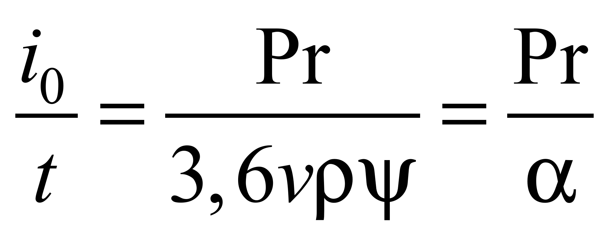 , (2)
, (2)
where
– is a value that takes into account characteristics of the cargo
and is calculated using dependence (1),
t m/l h;
 –
is a coefficient of bucket fill (according to the physical and
mechanical properties of cargo);
–
is a coefficient of bucket fill (according to the physical and
mechanical properties of cargo);
 – is a spacing of the buckets,
m;
– is a spacing of the buckets,
m;
 – is a cargo density, t/m3;
 – is a speed of the belt movement, m/s.
According to
the value of linear content of elevator’s bucket calculated from
the formula (2) the type and spacing of buckets in accordance with
the table 1 recommended by the wok [9]
are selected. Selection of buckets type depends on the properties of
the material, which is being transported. Deep buckets are used for
free-flowing, dusty and small pieced cargoes; the shallow ones –
for non-free-flowing cargoes.
To take
account physical and mechanical properties of the cargo, which is
being transported in further calculations let us construct the
correspondence tables of elevator parameters specified in the Table
1 to the performance value expressed by the formula (2) in the parts
of coefficient
.
The obtained data will be tabulated in the Tables 2, 3 for elevators
with deep and shallow buckets respectively.
Based on the design value of
elevator productivity and the type of material, which is being
transported according to the Tables 2 and 3, the bucket parameters,
their spacing on the belt and the required width of the belt are
selected. Characteristics of deep and shallow buckets are shown in
the Tab. 4.
Table 1
Value
of linear content of buckets
|
Bucket
width
 ,
mm ,
mm
|
Belt
width
 ,
mm ,
mm
|
Spacing
of the buckets
 ,
mm ,
mm
|
Bucket
|
|
|
|
|
deep
|
shallow
|
|
|
|
|
 ,
l ,
l
|
 ,
l/m ,
l/m
|
,
l
|
,
l/m
|
|
1
|
2
|
3
|
4
|
5
|
6
|
7
|
|
100
|
125
|
200
|
0.2
|
1
|
0.1
|
0.5
|
|
125
|
150
|
320
|
0.4
|
1.3
|
0.2
|
0.66
|
|
160
|
200
|
320
|
0.6
|
2
|
0.35
|
1.17
|
|
200
|
250
|
400
|
1.3
|
3.24
|
0.75
|
1.87
|
|
250
|
300
|
400
|
2.0
|
5
|
1.4
|
3.5
|
|
320
|
400
|
500
|
4.0
|
8
|
2.7
|
5.4
|
|
400
|
500
|
500
|
6.3
|
12.6
|
4.2
|
8.4
|
|
500
|
650
|
630
|
12
|
19
|
-
|
-
|
|
650
|
800
|
630
|
18
|
28.6
|
-
|
-
|
|
800
|
1000
|
800
|
32
|
40
|
-
|
-
|
|
1000
|
1200
|
800
|
45
|
56.25
|
-
|
-
|
Table 2
Dependence of parameters of deep buckets
on the elevator’s
productivity
|
Bucket
width
,
mm
|
Belt
width
,
mm
|
Spacing
of the buckets
,
mm
|
Bucket
capacity
,
l
|
Elevator
productivity, t/h
|
|
100
125
160
200
250
320
400
500
650
800
1000
|
125
150
200
250
300
400
500
650
800
1000
1200
|
200
320
320
400
400
500
500
630
630
800
800
|
0.2
0.4
0.6
1.3
2.0
4.0
6.3
12
18
32
45
|
α
1.3α
2α
3.24α
5α
8α
12.6α
19α
28.6α
40α
56.25α
|
Table 3
Dependence of parameters of shallow buckets
on the elevator’s
productivity
|
Bucket
width,
mm
|
Belt
width
,
mm
|
Spacing
of the buckets
,
mm
|
Bucket
capacity
,
l
|
Elevator
productivity, t/h
|
|
100
125
160
200
250
320
400
|
125
150
200
250
300
400
500
|
200
320
320
400
400
500
500
|
0.1
0.2
0.35
0.75
1.4
2.7
4.2
|
0.5α
0.66α
1.17α
1.87α
3.5α
5.4α
8.4α
|
Table 4
Description of elevator
buckets
|
Bucket
type
|
Internal
size of bucket, mm
|
Bucket
capacity,

|
|
|
width
|
outreach

|
height
|

|
|
Rounded
deep one D
|
100
100
125
160
200
250
320
400
500
650
800
1000
|
50
75
90
105
125
140
175
195
235
250
285
310
|
65
80
95
110
135
150
190
210
255
275
325
355
|
25
25
30
35
40
45
55
60
75
80
85
95
|
0.1
0.2
0.4
0.6
1.3
2.0
4.0
6.3
12
18
32
45
|
|
Bucket
type
|
Internal
size of bucket, mm
|
Bucket
capacity,
|
|
width
|
outreach
|
height
|
|
|
Rounded
shallow one S
|
125
160
200
250
320
400
|
65
75
95
120
145
170
|
85
100
130
160
190
220
|
30
35
40
55
70
85
|
0.2
0.35
0.75
1.4
2.7
4.2
|
For
clearness of further research let us take the conveyor belt
according to State Standard 20-85 of the type BKNL-150 as traction
body of elevator. The actual number of spacer plates of the belt can
be 3-6.
The belt thickness is
determined by the formula
 , (3)
, (3)
where
 mm,
mm,
 mm – is
the thickness of rubber coatings from the working and non-working
sides of the belt;
mm – is
the thickness of rubber coatings from the working and non-working
sides of the belt;
 mm – is
the thickness of fabric insert ply,
mm – is
the thickness of fabric insert ply,
 – is the number of fabric insert plies.
The weight of one running meter
of belt is determined by the formula
 , (4)
, (4)
where
 kg/m3
– belt density.
kg/m3
– belt density.
Involving
the formulas (3)-(4)
in the calculation let us present the table of correspondence of
width and linear weight of the belt with a different number of
insert plies to design values of elevator productivity for deep and
shallow buckets.
Table 5
Linear
weight of belts for deep buckets
|
Bucket
width ,
mm ,
mm
|
Linear
weight of the belt at
 ,
N/m ,
N/m
|
Linear
weight of the belt at
 ,
N/m ,
N/m
|
Linear
weight of the belt at
 ,
N/m ,
N/m
|
Linear
weight of the belt at
 ,
N/m ,
N/m
|
Elevator
productivity, t/h
|
|
125
150
200
250
300
400
500
650
800
1000
1200
|
12.5
15.0
20.1
25.1
30.1
40.1
50.1
65.2
80.2
100.3
120.3
|
14.7
17.6
23.5
29.4
35.3
47.0
58.8
76.4
94.0
117.5
141.0
|
16.8
20.2
27.0
33.7
40.4
53.9
67.4
87.6
107.8
134.8
161.7
|
19.0
22.8
30.4
38.0
45.6
60.8
76.0
98.8
121.6
152.0
182.4
|
α
1.3α
2α
3.24α
5α
8α
12.6α
19α
28.6α
40α
56.25α
|
Table 6
Linear weight of belts for shallow
buckets
|
Bucket
width
,
mm
|
Linear
weight of the belt at
,
N/m
|
Linear
weight of the belt at
,
N/m
|
Linear
weight of the belt at
,
N/m
|
Linear
weight of the belt at
,
N/m
|
Elevator
productivity, t/h
|
|
125
150
200
250
300
400
500
|
12.5
15.0
20.1
25.1
30.1
40.1
50.1
|
14.7
17.6
23.5
29.4
35.3
47.0
58.8
|
16.8
20.2
27.0
33.7
40.4
53.9
67.4
|
19.0
22.8
30.4
38.0
45.6
60.8
76.0
|
0.5α
0.66α
1.17α
1.87α
3.5α
5.4α
8.4α
|
Distributed weight of cargo per
1 m of belt is determined by the formula:
 , (5)
, (5)
where
 – coefficient
depending on
the belt
speed, N·s/kg·m.
– coefficient
depending on
the belt
speed, N·s/kg·m.
The dependence of value of
distributed weight of cargo on the design productivity calculated by
the formula (5) is given in the Table 7.
Table 7
Distributed
weight of cargo
|
Bucket
width
,
mm
|
Distributed
cargo weight during operation of
elevator with shallow buckets
N/m
|
Elevator
productivity with shallow buckets, N/m
|
Distributed
cargo weight during operation of
elevator with deep buckets
N/m
|
Elevator
productivity with deep buckets, N/m
|
|
100
125
160
200
250
320
400
500
650
800
1000
|
0.5αλ
0.66αλ
1.17αλ
1.87αλ
3.5αλ
5.4αλ
8.4αλ
-
-
-
-
|
0.5α
0.66α
1.17α
1.87α
3.5α
5.4α
8.4α
-
-
-
-
|
αλ
1.3αλ
2αλ
3.24αλ
5αλ
8αλ
12.6αλ
19αλ
28.6αλ
40αλ
56.25αλ
|
α
1.3α
2α
3.24α
5α
8α
12.6α
19α
28.6α
40α
56.25α
|
Linear
weight of the belt
with buckets is
determined by
the formula:
 , (6)
, (6)
where
 – bucket weight,
kg (Tab.
8).
– bucket weight,
kg (Tab.
8).
Linear burden on the loaded
strand is determined using the formula:
 . (7)
. (7)
The
estimated weight of
deep and shallow buckets is given
in the Table 8
[9].
Involving
the formulas (6)-(7) in the calculation and taking into account data
from the Table 8 let us determine the dependency of linear load on
the loaded strand of elevator on the productivity values for deep
and shallow buckets. The obtained results of calculations for belts
with different number of insert plies
is presented in the Tables 9, 10.
Table
8
Estimated
mass of elevator’s buckets
|
Bucket
width, mm
|
Wall
thickness, mm
|
Weight
of one bucket, kg
|
|
,
|
|
Deep
|
Shallow
|
|
100
|
2
|
0.5
|
0.4
|
|
125
|
2
|
0.7
|
0.6
|
|
160
|
2
|
0.9
|
0.7
|
|
200
|
3
|
2
|
1.5
|
|
250
|
3
|
3
|
2
|
|
320
|
3
|
5
|
5
|
|
400
|
4
|
11
|
10
|
|
500
|
5
|
18
|
-
|
|
650
|
5
|
23
|
-
|
|
800
|
6
|
28
|
-
|
|
1000
|
6
|
33
|
-
|
Table
9
The
linear load on the loaded strand for deep buckets
|
Bucket
width
,
mm
|
Distributed
weight of cargo
 ,
N/m ,
N/m
|
Linear
load on loaded strand at the belt with
 ,
N/m ,
N/m
|
Linear
load on loaded strand at the belt with
,
N/m
|
Linear
load on loaded strand at the belt with
,
N/m
|
Linear
load on loaded strand at the belt with
,
N/m
|
Elevator
productivity, t/h
|
|
100
125
160
200
250
320
400
500
650
800
1000
|
αλ
1.3αλ
2αλ
3.24αλ
5αλ
8αλ
12.6αλ
19αλ
28.6αλ
40αλ
56.25αλ
|
37+αλ
36.4+1.3αλ
47.7+2αλ
74.1+3.24αλ
103.6+5αλ
138.1+8αλ
265.7+12.6αλ
345.2+19αλ
438+28.6αλ
443.3+40αλ
524.6+56.3αλ
|
39.2+αλ
39+1.3αλ
51.1+2αλ
78.4+3.24αλ
108.8+5αλ
145+8αλ
274.4+12.6αλ
356.4+19αλ
451.8+28.6αλ
460.5+40αλ
545.3+56.3αλ
|
41.3+αλ
41.6+1.3αλ
54.6+2αλ
82.7+3.24αλ
113.9+5αλ
151.1+8αλ
283+12.6αλ
367.6+19αλ
465.6+28.6αλ
477.8+40αλ
566+56.3αλ
|
43.5+αλ
44.2+1.3αλ
58+2αλ
87+3.24αλ
119.1+5αλ
158+8αλ
291.6+12.6αλ
378.8+19αλ
479.4+28.6αλ
495+40αλ
586.7+56.3αλ
|
α
1.3α
2α
3.24α
5α
8α
12.6α
19α
28.6α
40α
56.25α
|
Table 10
The
linear load on the loaded strand for shallow buckets
|
Bucket
width
,
mm
|
Distributed
weight of cargo
,
N/m
|
Linear
load on loaded strand at the belt with
,
N/m
|
Linear
load on loaded strand at the belt with
,
N/m
|
Linear
load on loaded strand at the belt with
,
N/m
|
Linear
load on loaded strand at the belt with
,
N/m
|
Elevator
productivity, t/h
|
|
1
|
2
|
3
|
4
|
5
|
6
|
7
|
|
100
|
0.5αλ
|
32.1+0.5αλ
|
34.3+0.5αλ
|
36.4+0.5αλ
|
38.6+0.5αλ
|
0.5α
|
|
1
|
2
|
3
|
4
|
5
|
6
|
7
|
|
125
160
200
250
320
400
|
0.66αλ
1.17αλ
1.87αλ
3.5αλ
5.4αλ
8.4αλ
|
33.4+0.66αλ
41.5+1.17αλ
61.9+1.87αλ
79.1+3.5αλ
138.1+5.4αλ
246.1+8.4αλ
|
36+0.66αλ
44.9+1.17αλ
66.2+1.87αλ
84.3+3.5αλ
145+5.4αλ
254.8+8.4αλ
|
37.8+0.66αλ
48.4+1.17αλ
70.5+1.87αλ
89.4+3.5αλ
151.1+5.4αλ
263.4+8.4αλ
|
40.4+0.66αλ
51.8+1.17αλ
74.8+1.87αλ
94.6+3.5αλ
158+5.4αλ
272+8.4αλ
|
0.66α
1.17α
1.87α
3.5α
5.4α
8.4α
|
Traction
calculation of inclined bucket elevator is performed by the method
of encirclement, the basic principle of which is to identify
specific points of the track where the belt tension is changed. At
this tension in the next ( )
point is equal to the sum of belt tension in this ()
point and the belt movement resistance in the area between these
points:
)
point is equal to the sum of belt tension in this ()
point and the belt movement resistance in the area between these
points:
 . (8)
. (8)
In case of
drive drum rotation (Fig. 1) in clockwise order the minimum tension
will be at the point 2 –
 .
This tension in the belt during normal scooping satisfies the
following condition:
.
This tension in the belt during normal scooping satisfies the
following condition:
 .
(9)
.
(9)
The belt
tension force at the point 3 consists of tension force,
drum resistance and resistance to scooping of cargo :
:
 , (10)
where
 – coefficient of
tension increase in the belt with buckets
when bending around the drum.
– coefficient of
tension increase in the belt with buckets
when bending around the drum.
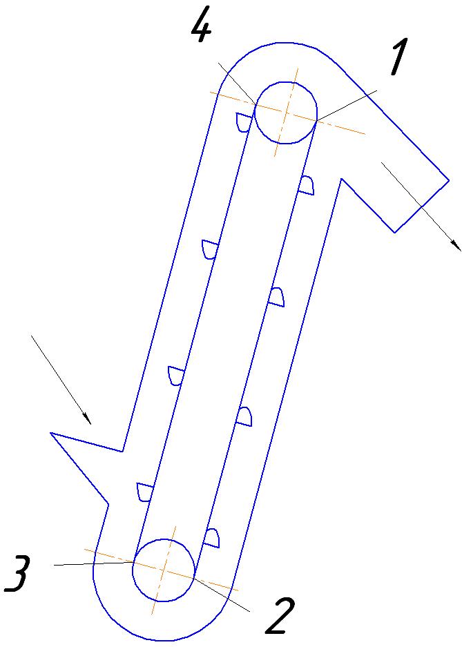
Fig. 1. Scheme of inclined bucket elevator
Resistance
to material scooping is determined using the formula:
 , (11)
where
 – is
a coefficient
of scooping
(Nm/kg),
which is determined by
specific work expended for
scooping of 1 kg
of material. At
the speed of buckets
– is
a coefficient
of scooping
(Nm/kg),
which is determined by
specific work expended for
scooping of 1 kg
of material. At
the speed of buckets
 m/s
m/s
 Nm/kg for powdered and small pieced materials, and
 Nm/kg – for
medium pieced material.
Nm/kg – for
medium pieced material.
Thus, substituting formulas (8)
and (11) to (10), we have:
 . (12)
Choosing the
value N m/kg (which meets all cargoes) we have:
 . (13)
We assume that the belt with
buckets at the track sections 3-4 and 1-2 (Fig. 1) is supported by
direct roller supports.
The specific weight of moving
parts of roller supports for loaded (section 3-4) and unloaded
(section 1-2) strands is determined by the formulas:
 . (14)
 . (15)
where
 – weight of
rotating parts of the upper and lower rolers.
– weight of
rotating parts of the upper and lower rolers.
For further calculations the
tables of estimated values of the distances between rollers of
loaded strand (Tab. 11) and the characteristics and sizes of roller
supports shown in the Table 12 will be used.
Ordinary
roller supports of the strand
1-2 are set with the spacing ,
twice as high as
,
twice as high as
 .
The dependence of the weight of ordinary roller supports on the belt
width is presented in the Table 12.
.
The dependence of the weight of ordinary roller supports on the belt
width is presented in the Table 12.
To
facilitate further studies, it is assumed that the cargo has a
density in the range of 1 … 2 t/m3.
Using the formulas (14)-(15)
let us present the values of specific weight of moving parts of
roller supports for loaded and unloaded strands depending on the
belt width and width of the bucket. Calculated values of the
specific weight will be presented in the Table 13.
Table
11
The estimated value of distances between supports
of loaded strand
|
Material
density
 ,
t/m3 ,
t/m3
|
Distances
between supports of loaded strand at
the belt width, mm
|
|
|
400
|
500
|
650
|
800
|
1000
|
1200
|
1400…1600
|
1800…2000
|
|
1
|
1500
|
1500
|
1400
|
1400
|
1300
|
1300
|
1200
|
1100
|
|
1…2
|
1400
|
1400
|
1300
|
1300
|
1200
|
1200
|
1100
|
1100
|
|
more than 2
|
1300
|
1300
|
1200
|
1200
|
1100
|
1100
|
1100
|
900
|
Table
12
Weight of ordinary direct roller supports
|
Belt
width B,
mm
|
Weight,
kg
|
|
400
|
6.0
|
|
500
|
7.5
|
|
650
|
10.5
|
|
800
|
18.5
|
|
1 000
|
22.0
|
|
1 200
|
25.0
|
Table 13
The estimated values of the specific weight of
moving parts of roller supports
for
loaded and unloaded strands
|
Specific weight of moving
parts
|
Bucket
width
,
mm
|
|
|
320
|
400
|
500
|
650
|
800
|
1000
|
|
loaded strand
 ,
N/m ,
N/m
|
40
|
50
|
75
|
132
|
169
|
192
|
|
uloaded strand
 ,
N/m ,
N/m
|
20
|
25
|
37.5
|
66
|
84.5
|
96
|
For
clearness of further calculations at the buckets with width less
than 320 mm, let us take the value of specific weight of moving
parts of roller supports for loaded and unloaded strands branches
 N/m,
N/m,
 N/m, respectively. We also accept that working conditions of the
elevator will be difficult; therefore, the resistance coefficient of
the belt movement along the rollers in future will be equal to 0.03.
N/m, respectively. We also accept that working conditions of the
elevator will be difficult; therefore, the resistance coefficient of
the belt movement along the rollers in future will be equal to 0.03.
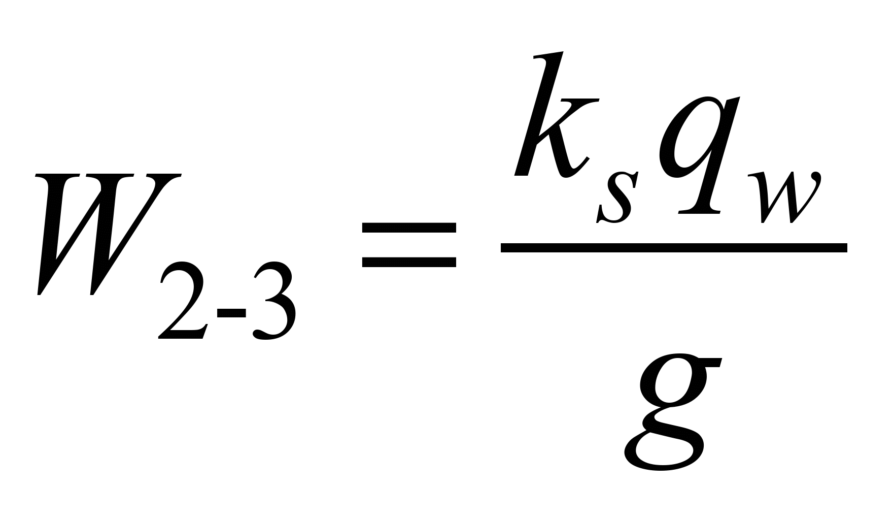
Traction
forces at the points 1 and
4 are determined using the formulas:

 , (16)
 , (17)
where
 – lift height of cargo,
m;
– lift height of cargo,
m;
 – inclination angle of elevator,
degree;
– inclination angle of elevator,
degree;
 – resistance coefficient of the belt
movement along the rollers.
– resistance coefficient of the belt
movement along the rollers.
The
dependence of traction forces values at the point 4 calculated by
the formula (16) on the value of design productivity, bucket type
and amount of insert plies are summarized in the Tables 14-15.
The
dependence of the values of tension force at the point 1 calculated
by the formula (17) on the value of design productivity, bucket type
and amount of insert plies of the belt are
summarized in the Tables
16-17.
Tractive effort accounting
rotational resistance of the drive drum is determined using the
formula:
 , (18)
where
 – is a
resistance coefficient
of drive drum rotation.
– is a
resistance coefficient
of drive drum rotation.
After
algebraic transformations
in the
formula (18)
we have:
 . (19)
The values
of tractive effort taking into account the drum rotation resistance
depending on the values of design performance, bucket type (deep and
shallow) and the number of insert plies of the belt are summarized
in the Tables 18-19.
Table 14
Traction
force at the point 4 at deep buckets
|
Bucket
width
,
mm
|
Traction
force at the belt with
 ,
N ,
N
|
Traction
force at the belt with
,
N
|
Traction
force at the belt with
,
N
|
Traction
force at the belt with
,
N
|
Elevator
productivity, t/h
|
|
100
|
37H+αλ
(7.95+H)+
+(77+αλ)
cHctgβ
|
39.2H+αλ
(7.95+H)+
+(79.2+αλ)
cHctgβ
|
41.3H+αλ(7.95+H)+
+(81.3+αλ)
cHctgβ
|
43.5H+αλ
(7.95+H)+
+(83.5+αλ)
cHctgβ
|
α
|
|
125
|
36.4H+1.3αλ(7.95+H)+
+(76.4+1.3αλ)cHctgβ
|
39H+1.3αλ
(7.95+H)+
+(79+1.3αλ)cHctgβ
|
41.6H+1.3αλ(7.95+H)
+(81.6+1.3αλ)
cHctgβ
|
44.2H+1.3αλ
(7.95+H)
+(84.2+1.3αλ)
cHctgβ
|
1.3α
|
|
160
|
47.7H+2αλ
(7.95+H)+
+(87.7+2αλ)
cHctgβ
|
51.1H+2αλ
(7.95+H)+
+(91.1+2αλ)
cHctgβ
|
54.6H+2αλ(7.95+H)+
+(94.6+2αλ)
cHctgβ
|
58H+2αλ
(7.95+H)+
+(98+2αλ)
cHctgβ
|
2α
|
|
200
|
74.1H+3.24αλ(7.95+H)
+(114.1+3.24αλ)cHctgβ
|
78.4H+3.24αλ(7.95+H)+
+(118.4+3.24αλ)
cHctgβ
|
82.7H+3.24αλ(7.95+H)
+(122.7+3.24αλ)cHctgβ
|
87H+3.24αλ
(7.95+H)+
+(127+3.24αλ)
cHctgβ
|
3.24α
|
|
250
|
103.6H+5αλ
(7.95+H)+
+(143.6+5αλ)
cHctgβ
|
108.8H+5αλ
(7.95+H)+
+(148.8+5αλ)
cHctgβ
|
113.9H+5αλ(7.95+H)+
+(153.9+5αλ)
cHctgβ
|
119.1H+5αλ
(7.95+H)
+(159.1+5αλ)
cHctgβ
|
5α
|
|
320
|
138.1H+8αλ
(7.95+H)+
+(178.1+8αλ)
cHctgβ
|
145H+8αλ
(7.95+H)+
+(185+8αλ)
cHctgβ
|
151.1H+8αλ(7.95+H)+
+(191.1+8αλ)
cHctgβ
|
158H+8αλ(7.95+H)+
+(198+8αλ)
cHctgβ
|
8α
|
|
400
|
265H+12.6αλ(7.95+H)
+(315.7+12.6αλ)cHctgβ
|
274.4H+12.6αλ(7.95+H)
+(324.4+12.6αλ)
cHctgβ
|
283H+12.6αλ(7.95+H)
+(333+12.6αλ)
cHctgβ
|
291.6H+12.6αλ(7.95+H)
+(341.6+12.6αλ)
cHctgβ
|
12.6α
|
|
500
|
345.2H+19αλ
(7.95+H)
+(420.2+19αλ)
cHctgβ
|
356.4H+19αλ(7.95+H)
+(431.4+19αλ)
cHctgβ
|
367.6H+19αλ(7.95+H)
+(442.6+19αλ)
cHctgβ
|
378.8H+19αλ(7.95+H)
+(453.8+19αλ)
cHctgβ
|
19α
|
|
650
|
438H+28.6αλ
(7.95+H)
+(570+28.6αλ)
cHctgβ
|
451.8H+28.6αλ(7.95+H)
+(583.8+28.6αλ)
cHctgβ
|
465H+28.6αλ(7.95+H)
+(597.6+28.6αλ)cHctgβ
|
479.4H+28.6αλ(7.95+H)
+(611.4+28.6αλ)
cHctgβ
|
28.6α
|
|
800
|
443.3H+40αλ
(7.95+H)
+(612.3+40αλ)
cHctgβ
|
460.5H+40αλ(7.95+H)
+(629.5+40αλ)
cHctgβ
|
477.8H+40αλ(7.95+H)
+(646.8+40αλ)
cHctgβ
|
495H+40αλ(7.95+H)+
+(664+40αλ)
cHctgβ
|
40α
|
|
1000
|
524H+56.3αλ(7.95+H)
+(716.6+56.3αλ)cHctgβ
|
545.3H+56.3αλ(7.95+H)
+(737.3+56.3αλ)
cHctgβ
|
566H+56.3αλ(7.95+H)+
+(758+56.3αλ)
cHctgβ
|
586.7H+56.3αλ(7.95+H)
+(778.7+56.3αλ)
cHctgβ
|
56.25α
|
Table 15
Traction force at the
point 4 at shallow buckets
|
Bucket
width
,
mm
|
Traction
force at the belt with
,
N
|
Traction
force at the belt with
,
N
|
Traction
force at the belt with
,
N
|
Traction
force at the belt with
,
N
|
Elevator
productivity, t/h
|
|
100
|
32.1H+0.5αλ(7.95+H)
+(72.1+0.5αλ)
cHctgβ
|
34.3H+0.5αλ(7.95+H)
+(74.3+0.5αλ) cHctgβ
|
36.4H+0.5αλ(7.95+H)
+(76.4+0.5αλ) cHctgβ
|
38.6H+0.5αλ(7.95+H)
+(78.6+0.5αλ) cHctgβ
|
0.5α
|
|
125
|
33.4H+0.66αλ(7.95+H)+(73.4+0.66αλ)
cHctgβ
|
36H+0.66αλ
(7.95+H)
+(76+0.66αλ) cHctgβ
|
37.8H+0.66αλ(7.95+H)
+(77.8+0.66αλ) cHctgβ
|
40.4H+0.66αλ(7.95+H)
+(80.4+0.66αλ) cHctgβ
|
0.66α
|
|
160
|
41.5H+1.17αλ(7.95+H)
+(81.5+1.17αλ) cHctgβ
|
44.9H+1.17αλ(7.95+H)
+(84.9+1.17αλ) cHctgβ
|
48.4H+1.17αλ(7.95+H)
+(88.4+1.17αλ) cHctgβ
|
51.8H+1.17αλ(7.95+H)
+(91.8+1.17αλ) cHctgβ
|
1.17α
|
|
200
|
61.9H+1.87αλ(7.95+H)
+(101.9+1.87αλ)cHctgβ
|
66.2H+1.87αλ(7.95+H)
+(106.2+1.87αλ)cHctgβ
|
70.5H+1.87αλ(7.95+H)
+(110.5+1.87αλ)cHctgβ
|
74.8H+1.87αλ(7.95+H)
+(114.8+1.87αλ)cHctgβ
|
1.87α
|
|
250
|
79.1H+3.5αλ(7.95+H)+
+(119.1+3.5αλ)cHctgβ
|
84.3H+3.5αλ(7.95+H)+
+(124.3+3.5αλ)cHctgβ
|
89.4H+3.5αλ(7.95+H)+
+(139.4+3.5αλ)cHctgβ
|
94.6H+3.5αλ
(7.95+H)
+(134.6+3.5αλ)cHctgβ
|
3.5α
|
|
320
|
138.1H+5.4αλ(7.95+H)
+(178.1+5.4αλ)cHctgβ
|
145H+5.4αλ
(7.95+H)
+(185+5.4αλ)cHctgβ
|
151.1H+5.4αλ(7.95+H)
+(191.1+5.4αλ)cHctgβ
|
158H+5.4αλ
(7.95+H)+
+(198+5.4αλ)cHctgβ
|
5.4α
|
|
400
|
246.1H+8.4αλ(7.95+H)
+(296.1+8.4αλ)cHctgβ
|
254.8H+8.4αλ(7.95+H)
+(304.8+8.4αλ)cHctgβ
|
263.4H+8.4αλ(7.95+H)
+(313.4+8.4αλ)cHctgβ
|
272H+8.4αλ
(7.95+H)+
+(322+8.4αλ)cHctgβ
|
8.4α
|
Table 16
Traction force at the
point 1 at deep buckets
|
Bucket
width
,
mm
|
Traction
force at the belt with
 ,
N ,
N
|
Traction
force at the belt with
,
N
|
Traction
force at the belt with
,
N
|
Traction
force at the belt with
,
N
|
Elevator
productivity, t/h
|
|
1
|
2
|
3
|
4
|
5
|
6
|
|
100
|
37H+5αλ+
+57cHctgβ
|
39.2H+5αλ+
+59.2cHctgβ
|
41.3H+5αλ+
+61.3cHctgβ
|
43.5H+5αλ+
+63.5cHctgβ
|
α
|
|
125
|
36.4H+6.5αλ+
+56.4cHctgβ
|
39H+6.5αλ+
+59cHctgβ
|
41.6H+6.5αλ+
+61.6cHctgβ
|
44.2H+6.5αλ+
+64.2cHctgβ
|
1.3α
|
|
160
|
47.7H+10αλ+
+67.7cHctgβ
|
51.1H+10αλ+
+71.1cHctgβ
|
54.6H+10αλ+
+74.6cHctgβ
|
58H+10αλ+
+78cHctgβ
|
2α
|
End of
table 16
|
Bucket
width
,
mm
|
Traction
force at the belt with
,
N
|
Traction
force at the belt with
,
N
|
Traction
force at the belt with
,
N
|
Traction
force at the belt with
,
N
|
Elevator
productivity, t/h
|
|
1
|
2
|
3
|
4
|
5
|
6
|
|
200
|
74.1H+16.2αλ+
+94.1cHctgβ
|
78.4H+16.2αλ+
+98.4cHctgβ
|
82.7H+16.2αλ+
+102.7cHctgβ
|
87H+16.2αλ+
+97cHctgβ
|
3.24α
|
|
250
|
103.6H+25αλ+
+123.6cHctgβ
|
108.8H+25αλ+
+128.8cHctgβ
|
113.9H+25αλ+
+133.9cHctgβ
|
119.1H+25αλ+
+139.1cHctgβ
|
5α
|
|
320
|
138.1H+40αλ+
+158.1cHctgβ
|
145H+40αλ+
+165cHctgβ
|
151.1H+40αλ+
+171.1cHctgβ
|
158H+40αλ+
+178cHctgβ
|
8α
|
Table 17
Traction
force at the point 1 at shallow buckets
|
Bucket
width
,
mm
|
Tractive
effort at the belt with
,
N
|
Tractive
effort at the belt with
,
N
|
Tractive
effort at the belt with
,
N
|
Tractive
effort at the belt with
,
N
|
Elevator
productivity, t/h
|
|
100
|
32.1H+2.5αλ+
+52.1cHctgβ
|
34.3H+2.5αλ+
+54.3cHctgβ
|
36.4H+2.5αλ+
+56.4cHctgβ
|
38.6H+2.5αλ+
+58.6cHctgβ
|
0.5α
|
|
125
|
33.4H+3.3αλ+
+53.4cHctgβ
|
36H+3.3αλ+
+56cHctgβ
|
37.8H+3.3αλ+
+57.8cHctgβ
|
40.4H+3.3αλ+
+60.4cHctgβ
|
0.66α
|
|
160
|
41.5H+5.85αλ+
+61.5cHctgβ
|
44.9H+5.85αλ+
+64.9cHctgβ
|
48.4H+5.85αλ+
+68.4cHctgβ
|
51.8H+5.85αλ+
+71.8cHctgβ
|
1.17α
|
|
200
|
61.9H+9.35αλ+
+81.9cHctgβ
|
66.2H+9.35αλ+
+86.2cHctgβ
|
70.5H+9.35αλ+
+90.5cHctgβ
|
74.8H+9.35αλ+
+94.8cHctgβ
|
1.87α
|
|
250
|
79.1H+17.5αλ+
+99.1cHctgβ
|
84.3H+17.5αλ+
+104.3cHctgβ
|
89.4H+17.5αλ+
+109.4cHctgβ
|
94.6H+17.5αλ+
+114.6cHctgβ
|
3.5α
|
|
320
|
138.1H+27αλ+
+158.1cHctgβ
|
145H+27αλ+
+165cHctgβ
|
151.1H+27αλ+
+171.1cHctgβ
|
158H+27αλ+
+178cHctgβ
|
5.4α
|
|
400
|
246.1H+42αλ+
+271.1cHctgβ
|
254.8H+42αλ+
+279.8cHctgβ
|
263.4H+42αλ+
+288.4cHctgβ
|
272H+42αλ+
+297cHctgβ
|
8.4α
|
Table 18
Tractive
effort on the drive drum at deep buckets
|
Bucket
width
,
mm
|
Tractive
effort at the belt with
 ,
N ,
N
|
Tractive
effort at the belt with
,
N
|
Tractive
effort at the belt with
,
N
|
Tractive
effort at the belt with
,
N
|
Elevator
productivity, t/h
|
|
1
|
2
|
3
|
4
|
5
|
6
|
|
100
|
5.9H+αλ(4+1.08H)+
+(30.7+1.08αλ)cHctgβ
|
6.3H+αλ
(4+1.08H)+
+(31.1+1.08αλ)cHctgβ
|
6.6H+αλ
(4+1.08H)+
+(31.4+1.08αλ)cHctgβ
|
7H+αλ
(4+1.08H)+
+(31.8+1.08αλ)cHctgβ
|
α
|
|
125
|
5.82H+1.3αλ(4+1.08H)
+(30.6+1.4αλ)
cHctgβ
|
6.2H+1.3αλ
(4+1.08H)
+(31+1.4αλ)
cHctgβ
|
6.7H+1.3αλ
(4+1.08H)
+(31.5+1.4αλ)
cHctgβ
|
7.1H+1.3αλ
(4+1.08H)+
+(31.9+1.4αλ)
cHctgβ
|
1.3α
|
|
160
|
7.63H+2αλ
(4+1.08H)
+(32.4+2.16αλ)
cHctgβ
|
8.2H+2αλ
(4+1.08H)+
+(33+2.16αλ)
cHctgβ
|
8.7H+2αλ
(4+1.08H)+
+(33.5+2.16αλ)
cHctgβ
|
9.3H+2αλ
(4+1.08H)+
+(34.1+2.16αλ)
cHctgβ
|
2α
|
|
200
|
11.9H+3.24αλ(4+1.08H)
+(36.7+3.5αλ)
cHctgβ
|
12.5H+3.24αλ(4+1.08H)
+(37.3+3.5αλ)
cHctgβ
|
13.2H+3.24αλ(4+1.08H)
+(38
+3.5αλ) cHctgβ
|
13.9H+3.24αλ
(4+1.08H)
+(38.7+3.5αλ)
cHctgβ
|
3.24α
|
|
250
|
16.6H+5αλ
(4+1.08H)+
+(41.4+5.4αλ)
cHctgβ
|
17.4H+5αλ
(4+1.08H)+
+(42.2+5.4αλ)
cHctgβ
|
18.2H+5αλ
(4+1.08H)+
+(43+5.4αλ)
cHctgβ
|
19.1H+5αλ
(4+1.08H)+
+(43.9+5.4αλ)
cHctgβ
|
5α
|
|
320
|
22.1H+8αλ
(4+1.08H)+
+(46.9+8.64αλ)
cHctgβ
|
23.2H+8αλ
(4+1.08H)+
+(48+8.64αλ)
cHctgβ
|
24.2H+8αλ
(4+1.08H)+
+(49+8.64αλ)
cHctgβ
|
25.3H+8αλ
(4+1.08H)+
+(50.1+8.64αλ)
cHctgβ
|
8α
|
|
400
|
42.5H+12.6αλ(4+1.08H)
+(73.5+13.6αλ)
cHctgβ
|
43.9H+12.6αλ(4+1.08H)
+(74.9+13.6αλ)
cHctgβ
|
45.3H+12.6αλ(4+1.08H)
+(76.3+13.6αλ)
cHctgβ
|
46.7H+12.6αλ
(4+1.08H)
+(77.7+13.6αλ)
cHctgβ
|
12.6α
|
|
500
|
55.2H+19αλ
(4+1.08H)+
+(101.7+20.5αλ)
cHctgβ
|
57H+19αλ
(4+1.08H)+
+(103.5+20.5αλ)
cHctgβ
|
58.8H+19αλ
(4+1.08H)
+(105.3+20.5αλ)
cHctgβ
|
60.6H+19αλ
(4+1.08H)
+(107.1+20.5αλ)
cHctgβ
|
19α
|
|
650
|
70.1H+28.6αλ(4+1.08H)
+(167.8+30.9αλ)
cHctgβ
|
72.3H+28.6αλ(4+1.08H)
+(170+30.9αλ)
cHctgβ
|
74.5H+28.6αλ(4+1.08H)
+(172.2+30.9αλ)
cHctgβ
|
76.7H+28.6αλ
(4+1.08H)
+(174.4+30.9αλ)
cHctgβ
|
28.6α
|
|
800
|
70.9H+40αλ
(4+1.08H)
+(196+43.2αλ)
cHctgβ
|
73.7H+40αλ
(4+1.08H)
+(198.8+43.2αλ)
cHctgβ
|
76.4H+40αλ
(4+1.08H)
+(201.5+43.2αλ)
cHctgβ
|
79.2H+40αλ
(4+1.08H)
+(204.3+43.2αλ)
cHctgβ
|
40α
|
|
1000
|
83.9H+56.3αλ(4+1.08H)
+(202.9+60.8αλ)
cHctgβ
|
87.2H+56.3αλ(4+1.08H)
+(206.2+60.8αλ)
cHctgβ
|
90.6H+56.3αλ(4+1.08H)
+(209.6+60.8αλ)
cHctgβ
|
93.9H+56.3αλ
(4+1.08H)
+(212.9+60.8αλ)
cHctgβ
|
56.25α
|
Table 19
Tractive effort on the drive drum at shallow
buckets
|
Bucket
width
,
mm
|
Tractive
effort at the belt with
,
N
,
N
|
Tractive
effort at the belt with
,
N
,
N
|
Tractive
effort at the belt with
,
N
,
N
|
Tractive
effort at the belt with
,
N
,
N
|
Elevator
productivity, t/h
|
|
100
|
5.1H+αλ
(4+1.08H)+
+(30+1.08αλ)
cHctgβ
|
5.5H+αλ
(4+1.08H)+
+(30.3+1.08αλ)cHctgβ
|
5.8H+αλ
(4+1.08H)+
+(30.6+1.08αλ)cHctgβ
|
6.2H+αλ
(4+1.08H)+
+(31+1.08αλ)
cHctgβ
|
0.5α
|
|
125
|
5.3H+1.3αλ(4+1.08H)
+(30.1+1.4αλ)
cHctgβ
|
5.8H+1.3αλ(4+1.08H)
+(30.6+1.4αλ)
cHctgβ
|
6.0H+1.3αλ(4+1.08H)
+(30.8+1.4αλ)
cHctgβ
|
6.5H+1.3αλ(4+1.08H)
+(31.3+1.4αλ)
cHctgβ
|
0.66α
|
|
160
|
6.6H+2αλ
(4+1.08H)+
+(31.4+2.16αλ)cHctgβ
|
7.2H+2αλ
(4+1.08H)+
+(32+2.16αλ)
cHctgβ
|
7.7H+2αλ
(4+1.08H)+
+(32.5+2.16αλ)cHctgβ
|
8.3H+2αλ
(4+1.08H)+
+(33.1+2.16αλ)cHctgβ
|
1.17α
|
|
200
|
9.9H+3.24αλ(4+1.08H)
+(34.7+3.5αλ)
cHctgβ
|
10.6H+3.24αλ(4+1.08H)
+(35.4+3.5αλ)
cHctgβ
|
11.3H+3.24αλ(4+1.08H)
+(36.1+3.5αλ)
cHctgβ
|
12H+3.24αλ
(4+1.08H)+
+(36.8+3.5αλ)
cHctgβ
|
1.87α
|
|
250
|
12.7H+5αλ
(4+1.08H)+
+(37.5+5.4αλ)
cHctgβ
|
13.5H+5αλ
(4+1.08H)+
+(38.3+5.4αλ)
cHctgβ
|
14.3H+5αλ
(4+1.08H)+
+(39.1+5.4αλ)
cHctgβ
|
15.1H+5αλ
(4+1.08H)+
+(39.9+5.4αλ)
cHctgβ
|
3.5α
|
|
320
|
22.1H+8αλ
(4+1.08H)+
+(46.9+8.6αλ)
cHctgβ
|
23.2H+8αλ
(4+1.08H)+
+(48+8.6αλ)
cHctgβ
|
24.2H+8αλ
(4+1.08H)+
+(49+8.6αλ)
cHctgβ
|
25.3H+8αλ
(4+1.08H)+
+(50.1+8.6αλ)
cHctgβ
|
5.4α
|
|
400
|
39.4H+12.6αλ(4+1.08H)
+(70.4+13.6αλ)
cHctgβ
|
40.8H+12.6αλ(4+1.08H)
+(71.8+13.6αλ)
cHctgβ
|
42.1H+12.6αλ(4+1.08H)
+(73.1+13.6αλ)
cHctgβ
|
43.5H+12.6αλ(4+1.08H)
+(74.5+13.6αλ)
cHctgβ
|
8.4α
|
Estimated kinematic scheme of
the elevator’s drive is shown in the Fig. 2.
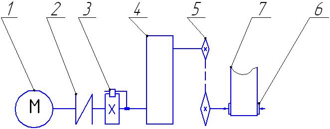
Fig. 2. Scheme of bucket elevator drive:
1
– engine; 2
– elastic clutch; 3
– locking device (ratchet);
4
– reducing gear; 5
– chain transmission; 6
– drive drum;
7
– belt
Efficiency coefficient of the
drive is determined by the formula:
 , (20)
where
 – efficiency coefficient of reducing gear;
 – efficiency coefficient of chain transmission;
 – efficiency coefficient of clutch.
Thus,
 .
.
Engine power
is determined by
the formula:
 . (21)
Calculated
power of the engine is determined
by the formula:
 , (22)
where
 – is
the safety factor.
– is
the safety factor.
Since
 and
and
 then using the formulas (21) and (22) we obtain the following:
 . (23)
Dependence
of the calculated engine power on the
values of design
performance,
bucket type, number of
insert plies of the belt,
speed of the belt movement
and lifting height of cargo calculated
using the formula (23) taking into account
data from the Tables
18-19 are summarized in the Tables
20-21:
Table
20
Calculated
power of engine at deep buckets
|
Bucket
width
,
mm
|
Engine
power at the belt with
 ,
W ,
W
|
Engine
power at the belt with
,
W
|
Engine
power at the belt with
,
W
|
Engine
power at the belt with
,
W
|
Elevator
productivity, t/h
|
|
1
|
2
|
3
|
4
|
5
|
6
|
|
100
|
v
[5.9H+αλ
(4+1.08H)+
+(30.7+1.08αλ)cHctgβ]
|
v
[6.3H+αλ
(4+1.08H)+
+(31.1+1.08αλ)cHctgβ]
|
v
[6.6H+αλ
(4+1.08H)+
+(31.4+1.08αλ)cHctgβ]
|
v[7H+αλ
(4+1.08H)+
+(31.8+1.08αλ)
cHctgβ]
|
α
|
|
125
|
[5.82H+1.3αλ(4+1.08H)
+(30.6+1.4αλ)cHctgβ]v
|
[6.2H+1.3αλ
(4+1.08H)
+(31+1.4αλ)
cHctgβ]v
|
[6.7H+1.3αλ
(4+1.08H)
+(31.5+1.4αλ)
cHctgβ]v
|
[7.1H+1.3αλ(4+1.08H)+
+(31.9+1.4αλ)cHctgβ]v
|
1.3α
|
|
160
|
v[7.63H+2αλ
(4+1.08H)
+(32.4+2.16αλ)
cHctgβ]
|
[8.2H+2αλ
(4+1.08H)+
+(33+2.16αλ)
cHctgβ]v
|
[8.7H+2αλ
(4+1.08H)+
+(33.5+2.16αλ)cHctgβ]v
|
v[9.3H+2αλ
(4+1.08H)+
+(34.1+2.16αλ)
cHctgβ]
|
2α
|
|
200
|
[11.9H+3.2αλ(4+1.08H)
+(36.7+3.5αλ)
cHctgβ]v
|
[12.5H+3.2αλ(4+1.08H)
+(37.3+3.5αλ)
cHctgβ]v
|
[13.2H+3.2αλ(4+1.08H)
+(38
+3.5αλ) cHctgβ]v
|
[13.9H+3.2αλ(4+1.08H)
+(38.7+3.5αλ)
cHctgβ]v
|
3.24α
|
|
250
|
[16.6H+5αλ
(4+1.08H)+
+(41.4+5.4αλ)
cHctgβ]v
|
[17.4H+5αλ
(4+1.08H)+
+(42.2+5.4αλ)
cHctgβ]v
|
[18.2H+5αλ(4+1.08H)+
+(43+5.4αλ)cHctgβ]v
|
[19.1H+5αλ
(4+1.08H)+
+(43.9+5.4αλ)
cHctgβ]v
|
5α
|
|
320
|
[22.1H+8αλ
(4+1.08H)+
+(46.9+8.64αλ)cHctgβ]v
|
[23.2H+8αλ
(4+1.08H)+
+(48+8.64αλ)
cHctgβ]v
|
[24.2H+8αλ
(4+1.08H)+
+(49+8.64αλ)cHctgβ]v
|
[25.3H+8αλ
(4+1.08H)+
+(50.1+8.64αλ)cHctgβ]v
|
8α
|
|
400
|
[42.5H+12.6αλ(4+1.08H)
+(73.5+13.6αλ)
cHctgβ]v
|
[43.9H+12.6αλ(4+1.08H)
+(74.9+13.6αλ)
cHctgβ]v
|
[45.3H+12.6αλ(4+1.08H)
+(76.3+13.6αλ)
cHctgβ]v
|
[46.7H+12.6αλ(4+1.08H)
+(77.7+13.6αλ)
cHctgβ]v
|
12.6α
|
|
500
|
[55,2H+19αλ
(4+1,08H)+
+(101,7+20,5αλ)cHctgβ]v
|
v[57H+19αλ
(4+1,08H)+
+(103,5+20,5αλ)
cHctgβ]
|
v[58,8H+19αλ
(4+1,08H)
+(105,3+20,5αλ)
cHctgβ]
|
v[60,6H+19αλ
(4+1,08H)
+(107,1+20,5αλ)
cHctgβ]
|
19α
|
|
650
|
[70,1H+28,6αλ(4+1,08H)
+(167,8+30,9αλ)cHctgβ]v
|
[72,3H+28,6αλ(4+1,08H)
+(170+30,9αλ)
cHctgβ]v
|
[74,5H+28,6αλ(4+1,08H)
+(172,2+30,9αλ)cHctgβ]v
|
[76,7H+28,6αλ(4+1,08H)
+(174,4+30,9αλ)cHctgβ]v
|
28,6α
|
|
800
|
[70,9H+40αλ
(4+1,08H)
+(196+43,2αλ)
cHctgβ]v
|
[73,7H+40αλ
(4+1,08H)
+(198,8+43,2αλ)cHctgβ]v
|
[76,4H+40αλ
(4+1,08H)
+(201,5+43,2αλ)cHctgβ]v
|
[79,2H+40αλ
(4+1,08H)
+(204,3+43,2αλ)cHctgβ]v
|
40α
|
|
1000
|
[83,9H+56,3αλ(4+1,08H)
+(202,9+60,8αλ)cHctgβ]v
|
[87,2H+56,3αλ(4+1,08H)
+(206,2+60,8αλ)cHctgβ]v
|
[90,6H+56,3αλ(4+1,08H)
+(209,6+60,8αλ)cHctgβ]v
|
[93,9H+56,3αλ(4+1,08H)
+(212,9+60,8αλ)cHctgβ]v
|
56,25α
|
Table 21
Calculated
power of engine at shallow buckets
|
Bucket
width
,
mm
|
Engine
power at the belt with
,
W
|
Engine
power at the belt with
,
W
|
Engine
power at the belt with
,
W
|
Engine
power at the belt with
,
W
|
Elevator
productivity, t/h
|
|
100
|
[5,1H+αλ
(4+1,08H)+
+(30+1,08αλ)
cHctgβ]v
|
v[5,5H+αλ
(4+1,08H)+
+(30,3+1,08αλ)
cHctgβ]
|
v[5,8H+αλ
(4+1,08H)+
+(30,6+1,08αλ)
cHctgβ]
|
v[6,2H+αλ
(4+1,08H)+
+(31+1,08αλ)
cHctgβ]
|
0,5α
|
|
125
|
[5,3H+1,3αλ(4+1,08H)+
+(30,1+1,4αλ)
cHctgβ]v
|
[5,8H+1,3αλ(4+1,08H)+
+(30,6+1,4αλ)
cHctgβ]v
|
[6,0H+1,3αλ(4+1,08H)+
+(30,8+1,4αλ)
cHctgβ]v
|
[6,5H+1,3αλ(4+1,08H)+
+(31,3+1,4αλ)
cHctgβ]v
|
0,66α
|
|
160
|
[6,6H+2αλ
(4+1,08H)+
+(31,4+2,16αλ)cHctgβ]v
|
[7,2H+2αλ
(4+1,08H)+
+(32+2,16αλ)
cHctgβ]v
|
[7,7H+2αλ
(4+1,08H)+
+(32,5+2,16αλ)cHctgβ]v
|
[8,3H+2αλ
(4+1,08H)+
+(33,1+2,16αλ)cHctgβ]v
|
1,17α
|
|
200
|
[9,9H+3,24αλ
(4+1,08H)
+(34,7+3,5αλ)
cHctgβ]v
|
[10,6H+3,2αλ(4+1,08H)
+(35,4+3,5αλ)
cHctgβ]v
|
[11,3H+3,2αλ(4+1,08H)
+(36,1+3,5αλ)
cHctgβ]v
|
[12H+3,24αλ(4+1,08H)
+(36,8+3,5αλ)
cHctgβ]v
|
1,87α
|
End of
table 21
|
Bucket
width
,
mm
|
Engine
power at the belt with
,
W
|
Engine
power at the belt with
,
W
|
Engine
power at the belt with
,
W
|
Engine
power at the belt with
,
W
|
Elevator
productivity, t/h
|
|
250
|
[12,7H+5αλ(4+1,08H)+
+(37,5+5,4αλ)
cHctgβ]v
|
[13,5H+5αλ
(4+1,08H)+
+(38,3+5,4αλ)
cHctgβ]v
|
[14,3H+5αλ
(4+1,08H)+
+(39,1+5,4αλ)
cHctgβ]v
|
[15,1H+5αλ
(4+1,08H)+
+(39,9+5,4αλ)
cHctgβ]v
|
3,5α
|
|
320
|
[22,1H+8αλ
(4+1,08H)+
+(46,9+8,6αλ)
cHctgβ]v
|
[23,2H+8αλ
(4+1,08H)+
+(48+8,6αλ)
cHctgβ]v
|
[24,2H+8αλ
(4+1,08H)+
+(49+8,6αλ)
cHctgβ]v
|
[25,3H+8αλ
(4+1,08H)+
+(50,1+8,6αλ)
cHctgβ]v
|
5,4α
|
|
400
|
[39,4H+12,6αλ(4+1,08H)
+(70,4+13,6αλ)
cHctgβ]v
|
[40,8H+12,6αλ(4+1,08H)
+(71,8+13,6αλ)
cHctgβ]v
|
[42,1H+12,6αλ(4+1,08H)
+(73,1+13,6αλ)
cHctgβ]v
|
[43,5H+12,6αλ(4+1,08H)
+(74,5+13,6αλ)
cHctgβ]v
|
8,4α
|
Findings
Let us
analyze the influence of design parameters of inclined bucket
elevator for transportation of fine coal on the power of required
drive. Taking into account the physical and mechanical properties of
fine coal according to the recommendations presented in the work [9]
it was selected the belt elevator with spaced deep buckets and
centrifugal discharge. The speed of belt movement is
 m/s;
fill factor of the bucket;
t/m3
–density of
fine coal; lift height of the cargo
m/s;
fill factor of the bucket;
t/m3
–density of
fine coal; lift height of the cargo
 m; inclination angle of elevator to the
horizontal
m; inclination angle of elevator to the
horizontal
 .
.
Under these
conditions the
coefficient are:
 (t m/l h);
 . (N/m)
At this
the dependence
of calculated
power of electric
engine of the elevator’s
bucket on the design performance is
given in the
Table 22:
Table
22
Calculated
power of the engine at deep buckets
|
Bucket
width
,
mm
|
Engine
power at the belt with
,
W
|
Engine
power at the belt with
,
W
|
Engine
power at the belt with
,
W
|
Engine
power at the belt with
,
W
|
Elevator
productivity, t/h
|
|
100
|
520
|
533
|
543
|
555
|
4.61
|
|
125
|
614
|
627
|
651
|
670
|
6
|
|
160
|
899
|
918
|
934
|
953
|
9.22
|
|
200
|
1438
|
1457
|
1480
|
1502
|
14.9
|
|
250
|
2158
|
2184
|
2210
|
2239
|
23.1
|
|
320
|
3306
|
3341
|
3373
|
3409
|
36.9
|
|
400
|
5452.5
|
5493
|
5538
|
5588
|
58.1
|
End of table 22
|
Bucket
width
,
mm
|
Engine
power at the belt with
,
W
|
Engine
power at the belt with
,
W
|
Engine
power at the belt with
,
W
|
Engine
power at the belt with
,
W
|
Elevator
productivity, t/h
|
|
500
|
7935
|
7988
|
8045
|
8109
|
87.6
|
|
650
|
11533
|
11603
|
11673
|
11746
|
131.8
|
|
800
|
15251
|
15341
|
15430
|
15519
|
184.4
|
|
1000
|
20939
|
21039
|
21144
|
21261
|
259.3
|
Taking into
account standard values
of power of
three-phase asynchronous squirrel cage
motors of 4A
series with
synchronous frequency of rotation 1000 rev/min for
the drive of
inclined elevator for
transportation of fine coal
it was compiled the table
of correspondence of design performance
and the required engine power.
Analyzing results of
calculations presented in the Table 23 it can be concluded that the
dependence of elevator drive power on its design performance (at
fixed lift height, type of cargo, the angle of inclination to
horizontal) in general is a piecewise constant monotonically
increasing function. At this the productivity values given in the
last column of the Table 23 should be considered as such, in which
the power value varies and is equal to the appropriate value given
in the second column of the Table 23. But to the value of 4.61 t/h
the power is 0.75 kW due to the minimum of such power in the engines
of such class. According to calculations it was plotted the
dependence of inclined elevator drive for fine coal transportation
on the value of design productivity (Fig. 3).
To determine
the graphic dependence of elevator drive power on its inclination
angle we take the initial data: transported material – fine coal;
productivity
 t/h lift height
m; speed of the belt movement
m/sec.
t/h lift height
m; speed of the belt movement
m/sec.
Taking into
account the fact that
 and
t/h for calculation of drive power the dependency in the 5th line
and first column will be used (Tab. 20).
and
t/h for calculation of drive power the dependency in the 5th line
and first column will be used (Tab. 20).
Substituting the initial data
for calculation into resulting dependence we obtain:
 . (24)
Graphic
dependence of value of elevator drive power when transporting fine
coal with design productivity
t/h on the angle of its inclination within
 is presented in the Fig. 4.
Table 23
Engine power at shallow buckets
|
Bucket
width
,
mm
|
Engine
power
,
kW
|
Engine
type
|
Elevator
productivity, t/h
|
|
100
125
160
200
250
320
400
500
650
800
1000
|
0.75
0.75
1.1
1.5
2.2
4.0
5.5
11.0
15.0
18.5
30
|
4А80А6У3
4А80А6У3
4А80В6У3
4А90L6У3
4А100L6У3
4А112MВ6У3
4А132S6У3
4А160S6У3
4А160M6У3
4А180M6У3
4А200M6У3
|
4.61
6
9.22
14.9
23.1
36.9
58.1
87.6
131.8
184.4
259.3
|
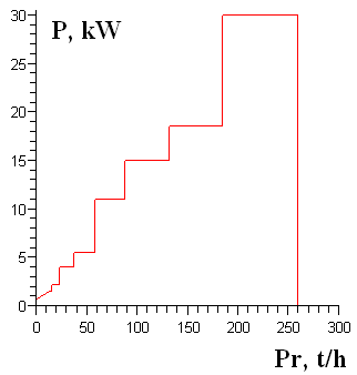
Fig. 3. Dependence of elevator drive power
on the productivity
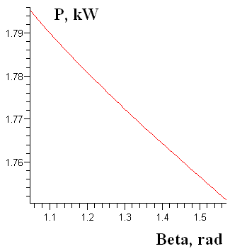
Fig. 4. Dependence of
elevator drive power
on
the angle of inclination
Originality and practical
value
It was plotted the analytical
dependence of elevator drive power on its design parameters (type
and characteristics of the cargo, lifting height, inclination angle,
productivity), which takes into account the standard sizes and types
of buckets and belts.
Using this dependence makes it
possible rapid determination of the approximate value of drive power
of inclined elevators with deep and shallow buckets and performing
high-quality selection of its key elements at the specific design
characteristics.
Based on the proposed
dependences it was plotted graphic dependence of power influence of
required inclined elevator’s drive on design productivity at the
fixed lift height, inclination angle, and the type of cargo. It was
also presented the graphic dependence of drive power on the
inclination angle of elevator at the other fixed design parameters.
Conclusions
For inclined belt bucket
elevators it was plotted analytical dependence of the drive power
value on its design parameters. This makes it possible to obtain the
required drive power value taking into account the type and physical
and mechanical properties of the cargo, the value of lift height,
inclination angle, design productivity and working conditions,
involving only one calculation formula. As an example of involving
the obtained results it was considered the process of plotting the
dependence of drive power on the design productivity of elevator for
fine coal transportation. For such elevator it was plotted the
parametric and graphic dependence of drive power on design
productivity and inclination angle of elevator taking into account
the standard parameters of buckets and properties of electric
engines. It was established that the function of varying the value
of elevator power on the design productivity (at fixed lifting
height, type of cargo¸ inclination angle) is piecewise and
monotonically increasing, and the dependence of elevator power value
on its inclination angle (at fixed design productivity, lift height,
load type, the speed of belt movement) is non-linear and
monotonically decreasing.
LIST OF REFERENCE LINKS
Александров,
М. П. Подъемно-транспортные
машины : учебник
/ М. П.
Александров. – Москва
: Высш. шк., 2000. – 522 с.
Богомаз,
В. М. Аналіз впливу проектних характеристик
елеватору на параметри його приводу
/ В. М. Богомаз // Наука та прогрес
транспорту. – 2015. – № 3 (57). – С.
162–175. doi:
10.15802/stp2015/46076.
Богомаз,
В. М. Дослідження впливу проектної
продуктивності елеватору на потужність
його приводу / В. М. Богомаз, К. Ц.
Главацький, О. А. Мазур // Наука та
прогрес транспорту. – 2015. – № 2 (56). –
С. 189–206. doi: 10.15802/stp2015/42178.
Богомаз,
В. М. Дослідження залежності
потужності приводу стрічкового конвеєру
від його проектних параметрів / В.
М. Богомаз // Наука та
прогрес транспорту. – 2016. – № 1 (61). –
С. 131–146. doi: 10.15802/stp2016/61024.
Зенков,
Р. Л. Машины непрерывного
транспорта : учебник
/ Р. Л. Зенков, И. И. Ивашков, Л. Н.
Колобов. – Москва : Машиностроение,
1987. – 432 с.
Іванченко,
Ф. К. Підйомно-транспортні машини :
підручник / Ф. К. Іванченко. – Київ :
Вища шк., 1993. – 413 с.
Катрюк,
И. С. Машины непрерывного
транспорта. Конструкции, проектирование
и эксплуатация : учеб.
пособие / И.
С. Катрюк, Е. В.
Мусияченко. – Красноярск :
ИПЦ КГТУ, 2006. – 266 с.
Кузьмин,
А. В. Справочник по расчетам механизмов
подъемно-транспортных
машин : учеб. пособие. – Минск
: Высш. шк., 1983. – 350 с.
Підйомно-транспортні
машини: розрахунки підіймальних і
транспортувальних машин : підручник
/ В. С. Бондарєв, О. І. Дубинець, М. П.
Колісник [та ін.].
– Київ : Вища шк., 2009. – 734 с.
Ракша,
С. В. Аналіз впливу пружних деформацій
несучого каната на зусилля в тяговому
канаті підвісної дороги / С. В. Ракша,
Ю. К. Горячов, О. С. Куроп’ятник // Наука
та прогрес транспорту. – 2013. – № 6 (48).
– С. 110–119. doi:
10.15802/stp2013/19686.
Расчет
и проектирование транспортных средств
непрерывного действия :
науч. пособие для вузов / А. И. Барышев,
В. А. Будишевский, А. А. Сулима, А. М.
Ткачук. – Донецк : Норд-Пресс, 2005. – 689
с.
Ромакин,
Н. Е. Машины непрерывного транспорта
: учеб. пособие / Н. Е. Ромакин.
– Москва : Издательский дом «Академия»,
2008. – 432 с.
Askari,
H. Nonlinear Oscillations Analysis of the Elevator Cable in a Drum
Drive Elevator System / H. Askari, D. Younesian, Z. Saadatnia
// Advances in Applied Mathematics and
Mechanics. – 2015.
– Vol. 7. – Iss. 01. – P. 43–57.
doi: 10.4208/aamm.2013.m225.
Failure
Analysis on Conveyer Chain Links of a Central Bucket Elevator /
J. Yin, O. Muvengei, J. Kihiu, K. Njoroge / J. of Mechanical and
Civil Engineering. – 2016.
– Vol. 13. –
Iss. 04. – P. 56–63.
doi: 10.9790/1684-1304075663.
Li,
S. C. Study on Elevator Drive System Dynamics Simulation of Rail
Transport Conveyer / S. C. Li, X. J. Wang // Applied Mechanics and
Materials. –
2014. – Vol.
511–512. –
P. 619–622.
doi:
10.4028/www.scientific.net/amm.511-512.619.
В. М. Богомаз1*,
М. В. БОРЕНКО2*,
С. В. ПАЦАНОВСЬКИЙ3*,
О. О. ТКАЧОВ4*
1*Каф.
«Військова підготовка спеціалістів
Державної спеціальної служби транспорту»,
Дніпропетровський
національний
університет залізничного транспорту
імені академіка В. Лазаряна, вул.
Лазаряна, 2, Дніпро, Україна, 49010, тел.
+38 (056) 373 19 09, ел. пошта wbogomas@i.ua, ORCID
0000-0001-5913-2671
2*Каф.
«Військова підготовка спеціалістів
Державної спеціальної служби транспорту»,
Дніпропетровський
національний
університет залізничного транспорту
імені академіка В. Лазаряна, вул.
Лазаряна, 2, Дніпро, Україна, 49010, тел.
+38 (056) 373 19 09, ел. пошта bmw1961@ukr.net, ORCID
0000-0001-9578-3906
3*Каф.
«Військова підготовка спеціалістів
Державної спеціальної служби транспорту»,
Дніпропетровський
національний
університет залізничного транспорту
імені академіка В. Лазаряна, вул.
Лазаряна, 2, Дніпро, Україна, 49010, тел.
+38 (056) 373 19 09, ел. пошта psven68@i.ua, ORCID
0000-0002-1628-3733
4*Каф.
«Військова підготовка спеціалістів
Державної спеціальної служби транспорту»,
Дніпропетровський
національний
університет залізничного транспорту
імені академіка В. Лазаряна, вул.
Лазаряна, 2, Дніпро, Україна, 49010, тел.
+38 (056) 373 19 09, ел. пошта otkachov@i.ua, ORCID
0000-0002-1857-7567
АНАЛІЗ ВПЛИВУ ПРОЕКТНИХ
ХАРАКТЕРИСТИК ПОХИЛОГО
КОВШОВОГО
ЕЛЕВАТОРУ
НА ПОТУЖНІСТЬ ЙОГО ПРИВОДУ
Мета. Одним
із основних елементів похилих стрічкових
ковшових елеваторів є їх привід. Для
визначення потужності приводу необхідно
провести розрахунки за стандартними
методиками, які приведені в сучасній
літературі. Основними проектними
параметрами таких елеваторів є
продуктивність, висота підйому, тип та
властивості транспортованого вантажу,
кут нахилу. В роботі необхідно побудувати
параметричну залежність потужності
приводу елеватору від його проектних
параметрів, яка враховувала б стандартні
розміри і типи ковшів та стрічок.
Методика.
Використовуючи методику тягового
розрахунку похилих стрічкових ківшевих
елеваторів, побудовано параметричні
залежності зусиль у характерних точках
траси елеватору, а також залежності
потужності приводу швидкохідних
елеваторів із глибокими та мілкими
ковшами від їх проектних параметрів
та характеристик. Результати.
На
основі побудованих
параметричних залежностей встановлено,
що функція зміни величини потужності
елеватору від проектної продуктивності
(при фіксованих висоті підйому, типі
вантажу, куті нахилу) є кусково-сталою
та монотонно зростаючою. Побудовано
графічну залежність потужності приводу
елеватору від кута нахилу в допустимих
межах його зміни. Отримана залежність
є нелінійною та монотонно спадаючою.
Визначені в загальному вигляді інтервали
проектних значень продуктивності, що
забезпечують постійну величину
потужності приводу похилого елеватору.
В якості прикладу залучення отриманих
результатів розглянуто процес побудови
залежностей потужності приводу від
проектної продуктивності та кута нахилу
елеватору для транспортування дрібного
вугілля. Наукова новизна.
Авторами вперше побудовані параметричні
залежності потужності приводу похилого
ківшевого елеватору від його проектних
параметрів, які враховують стандартні
розміри і типи ковшів та стрічок.
Практична значимість.
Використання побудованих залежностей
дає можливість відносно швидкого
визначення приблизного значення
потужності приводу похилих швидкохідних
елеваторів із глибокими та мілкими
ковшами на стадії проектування, а також
можливо виконати якісний підбір його
основних елементів при конкретних
проектних характеристиках: тип вантажу,
продуктивність, висота підйому, кут
нахилу.
Ключові слова: похилий елеватор;
ківш; привід; потужність; продуктивність;
вантаж; кут нахилу
В. Н. Богомаз1*, Н. В. Боренко2*,
С. В. ПАЦАНОВСКИЙ3*, А. А. Ткачов4*
1*Каф. «Военная
подготовка специалистов Государственной
специальной службы транспорта»,
Днепропетровский
национальний
университет железнодорожного транспорта
имени академика В. Лазаряна, вул.
Лазаряна, 2, Днипро,
Украина, 49010, тел.
+38 (056) 373 19 09, эл. почта wbogomas@i.ua,
ORCID 0000-0001-5913-2671
2*Каф.
«Военная подготовка специалистов
Государственной специальной службы
транспорта», Днепропетровский
национальний университет железнодорожного
транспорта имени академика В. Лазаряна,
вул. Лазаряна, 2, Днипро,
Украина,
49010, тел. +38 (056) 373 19 09, эл. почта
bmw1961@ukr.net,
ORCID 0000-0001-9578-3906
3*Каф.
«Военная подготовка специалистов
Государственной специальной службы
транспорта», Днепропетровский
национальний университет железнодорожного
транспорта имени академика В. Лазаряна,
вул. Лазаряна, 2, Днипро,
Украина,
49010, тел. +38 (056) 373 19 09, эл. почта psven68@i.ua,
ORCID 0000-0002-1628-3733
4*Каф.
«Военная подготовка специалистов
Государственной специальной службы
транспорта», Днепропетровский
национальний университет железнодорожного
транспорта имени академика В. Лазаряна,
вул. Лазаряна, 2, Днипро,
Украина,
49010, тел. +38 (056) 373 19 09, эл. почта otkachov@i.ua,
ORCID 0000-0002-1857-7567
АНАЛИЗ ВЛИЯНИЯ ПРОЕКТНЫХ
ХАРАКТЕРИСТИК НАКЛОННОГО
КОВШЕВОГО
ЭЛЕВАТОРА
НА МОЩНОСТЬ ЕГО ПРИВОДА
Цель. Одним
из основных элементов наклонных
ленточных ковшовых элеваторов является
их привод. Для определения мощности
привода необходимо провести расчеты
по стандартным методикам, которые
изложены в современной литературе.
Основными проектными параметрами
являются производительность, высота
подъема, тип и свойства транспортированного
материала, угол наклона. В работе
необходимо построить параметрическую
зависимость мощности привода элеватора
от его проектных параметров, которая
учитывала бы стандартные размеры и
типы ковшей и лент. Методика.
Используя методику тягового расчета
наклонных ленточных ковшовых элеваторов,
построены параметрические зависимости
усилий в характерных точках трассы
элеватора, а также зависимости мощности
привода быстроходных элеваторов с
глубокими и мелкими ковшами от их
проектных параметров и характеристик.
Результаты. На
основе построенных параметрических
зависимостей установлено, что функция
изменения величины мощности элеватора
от проектной производительности (при
фиксированных высоте подъема, типе
груза,
скорости движения ленты) является
кусочно-постоянной и монотонно
возрастающей. Построена графическая
зависимость мощности привода элеватора
от угла наклона в допустимых пределах
его изменения. Полученная зависимость
является нелинейной и монотонно
убывающей. Определены в общем виде
интервалы проектных значений
производительности, которые обеспечивают
постоянную величину мощности привода
наклонного элеватора. В качестве примера
применения полученных результатов
рассмотрен процесс построения зависимости
мощности привода от проектной
производительности и угла наклона
элеватора для транспортировки мелкого
угля. Научная новизна.
Авторами впервые построены параметрические
зависимости мощности привода наклонного
ковшевого элеватора от его проектных
параметров, которые учитывают стандартные
размеры и типы ковшей и лент. Практическая
значимость. Использование
построенных зависимостей дает возможность
относительно быстрого определения
приблизительного значения мощности
привода наклонных быстроходных
элеваторов с глубокими и мелкими ковшами
на стадии проектирования. А также можно
выполнить качественный подбор его
основных элементов при конкретных
проектных характеристиках: типе груза,
производительности, высоте подъема,
угле наклона.
Ключевые слова: наклонный элеватор;
ковш; привод; мощность; производительность;
груз; угол наклона
REFEReNCEs
Aleksandrov M.P.
Podyemno-transportnyye
mashiny
[Handling machinery].
Moscow, Vysshaya shkola Publ.,
2000. 522 p.
Bohomaz V.M. Analiz vplyvu proektnykh
kharakterystyk elevatoru na parametry yoho pryvodu [Influence
analyses of designed characteristics of the elevator to the
parameters of its drive]. Nauka ta
prohres transportu – Science and Transport Progress,
2015, no. 3 (57), pp. 162-175. doi: 10.15802/stp2015/46076.
Bohomaz V.M.,
Hlavatskyi
K.Ts.,
Mazur O.A.
Doslidzhennia
vplyvu
proektnoi
produktyvnosti
elevatoru na
potuzhnist yoho
pryvodu
[Research of influencing of project discriptions of elevator on
parameters of its drive]. Nauka
ta prohres transport –
Science and Transport Progress,
2015, no. 2
(56), pp.
189-206.
doi: 10.15802/stp2015/42178.
Bohomaz V.M. Doslidzhennia zalezhnosti
potuzhnosti pryvodu strichkovoho konveieru vid yoho proektnykh
parametriv [Research of dependence of belt conveyer drive power on
its design parameters].
Nauka ta prohres transportu
– Science and Transport
Progress,
2016, no. 1 (61), pp. 131-146. doi: 10.15802/stp2016/61024.
Zenkov R.L., Ivashkov I.I., Kolobov L.N. Mashiny
nepreryvnogo transporta [Stream-flow
transportation machines].
Moscow, Mashinostroyeniye Publ., 1987. 432 p.
Ivanchenko F.K.
Pidiomno-transportni mashyny
[Handling
machinery]. Kyiv, Vyshcha
shkola Publ., 1993. 413 p.
Katryuk, I. S., Musiyachenko Ye.V. Mashiny
nepreryvnogo transporta. Konstruktsii, proektirovaniye
i ekspluatatsiya [Stream-flow
transportation machines. Constructions,
designing and operation]. Krasnoyarsk,
IPTs KGTU Publ.,
2006. 266 p.
Kuzmin A.V. Spravochnik
po raschetam mekhanizmov podyemno-transportnykh mashin
[Reference book on calculation of
mechanisms of handling machinery].
Minsk, Vysshaya shkola Publ., 1983. 350 p.
Bondariev V.S., Dubynets O.I., Kolisnyk M.P.
Pidiomno-transportni mashyny:
rozrakhunky pidiimalnykh i transportuvalnykh mashyn [Handling
machinery: calculations
of lifting and transporting machines].
Kyiv,
Vyshcha shkola Publ.,
2009. 734 p.
Raksha S.V., Horiachov Yu.K., Kuropiatnyk O.S.
Analiz vplyvu pruzhnykh deformatsii nesuchoho kanata na zusyllia v
tiahovomu kanati pidvisnoi dorohy [Influence
analysis of elastic deformations of the track cable on efforts in
the hauling rope of aerial ropeway]. Nauka
ta prohres transportu –
Science and Transport Progress, 2013,
no. 6 (48), pp. 110-119. doi: 10.15802/stp2016/61024.
Baryshev A.I.,
Budishevskiy
V.A.,
Sulima A.A.,
Tkachuk A.M.
Raschet
i
proyektirovaniye
transportnykh
sredstv
nepreryvnogo
deystviya
[Calculation and design of stream-flow transportation machines].
Donetsk, Nord-Press
Publ., 2005. 689p.
Romakin N.Ye. Mashiny
nepreryvnogo transporta [Stream-flow
transportation machines].
Moscow, Akademiya Publ., 2008. 432 p.
Askari H., Younesian D., Saadatnic Z. Nonlinear
oscillations analysis of the elevator cable in a drum drive
elevator system. Advances in Applied
Mathematics and Mechanics, 2015, vol.
7, issue 01, pp. 43-57. doi: 10.4208/aamm.2013.m225.
Yin J., Muvengei O., Kihiu J., Njoroge K.
Failure analysis on conveyer chain links of a central bucket
elevator. Journal of Mechanical and
Civil Engineering, 2016, vol. 13,
issue 04, pp. 56-63. doi: 10.9790/1684-1304075663.
Li S.C., Wang X.J. Study on elevator drive
system dynamics simulation of rail transport conveyer. Applied
Mechanics and Materials, 2014, vol.
511-512, pp. 619-622. doi:
10.4028/www.scientific.net/amm.511-512.619.
Prof. S. V. Raksha, D. Sc.
(Tech.); Associate Prof. S. V. Shatov, D. Sc. (Tech.) recommended
this article to be published
Accessed: Sep. 07, 2016
Received: Dec. 29, 2016
doi
© V. M.
Bohomaz, M. V. Borenko, S. V.
Patsanovskiy, O. O. Tkachov, 2016