Introduction
The basis for
ensuring the traffic safety is systems for diagnosing the state of
infrastructure devices, which allow predicting their possible
failures and eliminating emergency situations in a timely
manner. A non-redundant link of electrified lines of railways and
urban electric transport is a contact network (CN), the failures
of which lead to delays of trains, urban electric transport and, as
a consequence, to economic damage [1–12]. An important feature
of the CN is its participation in the current collection, which
causes the appearance of loads requiring the improvement of
interaction models of current collectors with the CN and the
development of a theory of high-current contact to improve the
diagnostic systems [3, 14]. The uniqueness of the CN places high
demands both on the design of its devices and to the methods of
their technical operation [4, 7].
Reliable and
economical operation of the CN is impossible without automated
diagnostic devices that allow detecting the locations of
malfunctions or other aberrations, as well as analysing them to
develop managerial decisions to ensure the
uninterrupted movement of the rolling stock [9, 11–13, 16].
Railway and
industrial companies in many countries strive to eliminate
interruptions in the movement of trains and electric industrial and
urban electric transport through high-quality diagnostics of the CN
and malfunction repair. In this case, the economic aspect associated
with the optimization of the service life of the CN devices and,
first of all, the overhead wire (OW) plays the most important role
[7, 8].
Today, the
triangulation method for determining the height and zigzag of the
OW, the phase measuring method based on the use of light sources,
the method of monitoring the position of the video camera system and
OW wear are known in application. The existing methods are based on
one of two basic principles: contactless measurement or contact one,
when the sensor is installed on the current collector and touches
the overhead wire. Using the contactless systems, measurements can
be made at any movement speed, but the measurement accuracy is
reduced. Contact systems have higher accuracy, but they provide
measurements at low speeds [15, 17].
The optical
method of automatic control involves installation of several optical
systems on the roof of the laboratory car for testing the contact
network (LTCN), which films the catenary suspension with supporting
structures on the move from different points and transfers the
resulting images to a storage unit.
In the
measurement system, specialized high-speed television cameras are
used, and fan-shaped raster pulse laser illuminators are used to
illuminate the overhead wires.
On the German
Railways Network (DBAG), for monitoring small devices, such as bolt
heads or torn wire strands of the carrier cable, the optics
resolution is 1–2 mm, and the flash duration when illuminating the
object should not exceed 45 μs. When measuring the OW wear,
comparison with previous results is not required. A comparison with
the cross-section of the new wire is enough here. The measurement
accuracy of this type is 0.1 mm, and a decrease in the wire
thickness can be detected already at a length of 2–3 cm [15, 17].
In recent
years, qualitatively new diagnostic tools have been developed based
on video measuring systems. Their speed and detection reliability
when diagnosing the CN elements have been increased. Computing power
has been significantly increased, new more advanced photoreceiving
components and image processing algorithms have been developed [9,
13–17]. Therefore, there is a scientific problem of improving
video measuring diagnostics systems to ensure reliable and
economical current collection on electrified lines of railways and
urban electric transport.
Purpose
The main
purpose of the article is a systematic analysis of the state and
development prospects of electric traction networks of electrified
railways and urban electric transport, the development of hardware
and software for improving video measuring diagnostic tools and
expanding the functionality of laboratory cars for testing the
contact network.
Methodology
In our
opinion, in the current situation, it is necessary to solve the
problem of complete replacement of most of the devices of electric
traction networks of railways and urban electric transport by
investing significant funds in modernization. This is evidenced by
the experience of foreign countries. On many railway sections of
transport corridors, as well as in large cities, a new CN is
required, and only in this case safe and economical operation of the
power supply for train traction system and urban electric transport
will be ensured [6, 14].
The problem
of increasing the resolution capability of the quality control
systems of the current collectors and CN’s interaction from the
moving laboratory car was solved using a complex approach. This
approach includes theoretical analysis and experimental research of
the parameters of the control object – overhead wire (OW),
modelling of the control device of the wear of overhead wire and its
functional units, determination of factors influencing the control
error [3, 4, 7, 10]. At the same time, the apparatus of factorial
analysis, the theory of optoelectronic circuits and methods of
statistical information processing were used to determine the
theoretically maximum allowable error in monitoring the wear of the
OW and other components, from the point of view of the operation of
CN.
Findings
Analysis
of the state and development prospects of electric traction networks
of railways and urban electric transport. At
all stages of the development of railways, electrification was the
leading link in their reconstruction, qualitatively changing the
operational work (Fig. 1). For the period 1994–2011 more than 1700
km of the operational length of railways were electrified, the
polygon of electrified lines was increased by 21%, while the volume
of electric traffic increased to 89.7%. The highest electrification
rates were achieved in 2011–2012 on the sections of the
accelerated movement of passenger trains with an operational length
of 176 km. The specific weight of the length of electrified lines
increased to 47.3%, and the specific weight of electric cargo
turnover was more than 91.2% [1].
The task of
further electrification was planned in the volume of phased
implementation: in total for the period 2013–2020 – about 1 841
km. However, this program failed. At the same time, in recent years,
there has been a tendency for the development of urban electric
transport in large cities.
The rate of
ageing of power supply devices, given the existing funding
shortfall, continues to outstrip the rate of reconstruction. The
length of the electrified lines operated beyond the average period
(40 years) increased from 5012 km (or 52.0%) in 2007 to 6393 km (or
62.3%) in 2012, and in 2020 up to 6820 km (or 67.9%). Today, 73% of
the total number of traction substations of urban electric transport
operate with a service life of more than 40 years, and 43% with
a service life of more than 50 years.
Thus, a complete reconstruction of more
than 80% of the length of the contact network and traction
substations of urban electric transport is required. There is no
global experience in operating a contact network with such
ageing rates. Specific damage to CN, which has served for 40 years
or more, is 2.7 times higher than in the sections with a service
life of 10 years [1, 2].
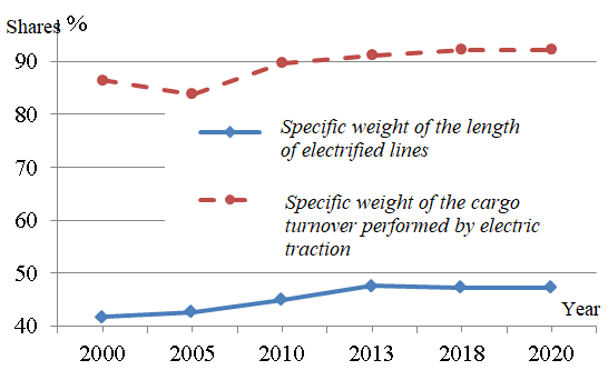
Fig. 1. Specific
weight of electric traction
in the railway network length and
in the total cargo turnover
Analysis of
the replacement dynamics of the main CN devices (Fig. 2) shows that
the average values and root-mean-square deviations (shown in
brackets) have the following values: overhead wire – 188 km (80
km); carrier cable – 134 km (79 km); high-voltage insulators –
40 thousand pcs. (17 thousand pieces); supports – 2340 pcs.
(751 pcs.). Thus, the existing rate of replacement of the main
devices of the CN is incommensurate to the rate of their ageing, and
since 2021, it can cause a snowballing growth of failures [2].
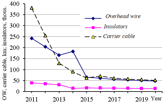
Fig. 2. Replacement
dynamics of the main
elements of the CN
Analysis of
the number of damages at all junctions of the CN of the railways for
different periods shows that the most often fail the overhead wire
and cables, insulators, droppers, clamps and parts. Fig. 3 shows
the failure dynamics of these devices for railways. This is
explained by the fact that structurally all other elements of the CN
are designed to support the OW in the set position. Failures of any
element of the CN often result in OW failure. On the other hand, the
OW is the element of CN that directly interacts with the current
collector. Interaction with the current collector during the current
collection process causes intensive ageing of wires and a large
number of sudden failures caused by malfunctions of the electric
rolling stock.
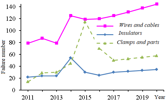
Fig. 3. Failure
dynamics of the most damageable catenary devices
Over the past
10 years, there has been a tendency for an increase in the number of
CN failures due to mechanical and electromechanical wear of
droppers, as well as clamps and parts. The height depletion of the
support structures, which occurred on a significant part of the
polygon due to multiple track repairs, also became a problem. The
specified problem can be solved only with the overhaul repair of the
CN [2].
Calculations
have shown that over the past 10 years, there have been changes
in the failure risks, which reflected the growth of ageing, wear and
degradation processes of the CN. The most significant is the risk of
OW failures. The risk of failures of catenary suspension and current
collectors in monetary terms is so great that it requires drastic
solutions in the field of investments both in overhaul repair or
construction of new catenary suspension and current collectors of
electric rolling stock, and in new systems for diagnostics of
current collection.
Analysis of
damage to power supply devices for urban electric transport shows
that the overwhelming amount of damage is accounted for by contact
networks, especially in the sections with a service life of more
than 40 years. Significantly less damage occurs at traction
substations (TS). Damage distribution by the types of devices: CN
– 49.7%; TS – 5.4%; cable lines and trackways –
44.6%.
The ratio
of mathematical expectations and root-mean-square deviations of
damage to the contact network and current collectors as a result of
delays of trams and trolleybuses in percent of the total number of
delays over the past 10 years are as follows: 194.5 and 15.5, which
is 64.3% and 3.4%, respectively.
The need to
expand tram and trolleybus lines and modernize power supply devices
in a resource-saving environment requires new technologies for the
design, construction and operation of infrastructure facilities. For
the first time in Kharkiv, a new generation of traction
substation with dry transformers, 12-pulse rectification circuits,
digital protection and equipment diagnostics was put into operation,
ensuring operation according to condition. It is necessary to create
automated systems for laboratory cars for testing CN of trams
(LTCN–T),
which recognize hidden defects in CN (Fig. 4), as well as
laboratories on the basis of trolley buses or trucks for trolleybus
CN. This task is posed in our country for the first time [7–12].
The modern
LTCN–T include an optical-mechanical unit; laser fast-acting
system for OW diagnostics; video surveillance and information
processing system; additional power supply system; complex control
panel and functional panel; rotation angle sensors, stresses,
lateral displacements, ambient temperature, car movement speed.
Fig. 4. LTCN–T:
а
– appearence; b
– workplace in the car;
c
– operation of the video surveillance system and information
processing synchronously
with the determination of the car
geolocation
LTCN–T
allows controlling the current height position, OW displacement; OW
suspension defects; OW wear; distance travelled; movement speed;
ambient air temperature; CN voltage; GLONASS/GPS coordinates; CN
state with the help of video recording.
The tram
laboratory for a comprehensive assessment of the infrastructure
state, in addition to the LTCN–T
parameters, allows performing measurements of track depression and
alignment, longitudinal track gradient, acceleration on the bogie
and body, track width, rail wear, CN support dimensions, as well as
video monitoring of the rail track, connections of assembling
joints, connection of supply cables, inter-rail connections.
For example,
a specialized video system (Fig. 4, c)
records a video image, the viewer of which is shown on the screen.
The programs work synchronously. This makes it possible to stop the
tape in the places where clarification is needed (for example, a
large zigzag), enter the video program at this place and take a
photo with the necessary comment to analyse, issue to the repair
site and for serviceability.
The use of
LTCN–T allows
obtaining objective data on the CN state, conducting an automated
assessment of the CN state by one or several passes, linking the
measurement results to a place on the map and performing video
surveillance of the CN infrastructure. All the above makes it
possible to create databases on the state of the contact network,
track, cable lines, etc., as well as the conditions for the
transition of their service by state. The solution of the problem
allows improving the assessment quality of the CN state and reducing
the possibility of failures, as well as ensuring energy and resource
saving in the process of passenger transportations.
Video
measuring systems for diagnostics of contact networks. In
recent years, hardware and software have been developed to improve
the system for measuring the OW parameters and other CN components.
A method for increasing the resolution of a stereo television
system and an adaptive lighting system is proposed. It consists in
preliminary image transformation and expansion of the dynamic range
of image measurement. The quality of CN diagnostics in difficult
conditions for video surveillance has been improved. A camera with a
built-in image compression module without loss of its fast action
has been proposed, which allows capturing and transmitting
full-frame images to a computer complex for the application of new
CN diagnosing algorithms [8, 10, 15, 16].
The stereo
television system is based on a specialized fast-acting television
camera of a new generation, and the lighting system can operate both
in continuous and in pulsed mode with a duration of light pulses
from 20 μs. Cameras can be equipped with lenses with automatic iris
control according to the P-iris standard; serial interface; serial
interfaces and high-speed video compression module and frame
grabber.
For the
enterprises of power supply of electrified railways, industrial and
urban electric transport, innovative means of complex diagnostics of
the CN state have been developed. They are laboratory cars, which
provide monitoring of OW wear, the state of high-voltage insulation,
heating of electrical connections, grounding of supports on rail.
An automated
video-measuring system for monitoring the CN supports grounding and
its other equipment, as well as elements of the track facilities
located in the visibility zone of specialized cameras, which ensure
the system's operability at any time of the day at speeds up to 160
km/h, is proposed: discretization of image lines along the track
length from 0.5 mm; the value of the electronic shutter at a speed
of 160 km/h is not more than 22 μs; the
number of pixels in a line is at least 1000. An air curtain
subsystem is implemented to protect the cameras.
Development
of new diagnostic tools for the contact network and improving the
efficiency of existing ones is a priority area of activity of
DAK-Energetika LLC, which carries out the entire range of works,
including research, design, manufacture, installation,
commissioning, warranty and service.
The
manufactured measuring equipment is included in the State Register
of Measuring Instruments
and Register of Measuring Instruments, Test Equipment and Methods of
Measurements Used in Ukrainian Railway
OJSC, and is
metrologically certified and protected by patents.
Improvement
of WEAR laser fast-acting system for measuring the parameters of the
contact wire. The Aptima MT9M413C36STC
video sensor used in the WEAR system has a 100-bit output data bus
that transmits a block of 10-bit brightness readings of 10
neighbouring pixels of the current line per one cycle of the
operating frequency fг.
Each line of the image has a size of 1280 pixels and is transmitted
in a block consisting of 128 fг
cycles. For contactless measuring of the
profile of the worn out OW part, measuring the position of the OW
relative to the current collector axis, detecting OW overturns and
lateral slopes of the OW clips (dropper, pull-off, etc.), LTCN
is equipped with WEAR
fast-acting laser diagnostic OW system.
This
diagnostic system belongs to the group of systems that measure OW
wear by its profile, their operating principle is indicated in [8,
10, 13].
The measuring
system consists of 8 laser fan-shaped emitters, in which the
collimated laser beam is converted into a flat fan out light beam
0.3–0.6 mm thick using a spreading system, and 4 matrix
television cameras. When the fan beam of light strikes the OW, a
visible line of its intersection with the plane is formed on the
wire surface, in which the correct beam lies. It is this
intersection line that is distinguished by the processing system
from the resulting image of the current frame of the television
camera. In this case, the shape of the fixed line weakly depends on
the OW inclination and is mainly determined by its wear. The program
provides the ability to display a 3-D OW model with imposed measured
wear for the selected camera (Fig. 5).
The use of
LED illumination, which effectively illuminates the entire surface
of the lower part of the overhead wire and clamps, together with the
possibility of obtaining a full frame of the image at the input of
the information-computing complex, can significantly increase the
informativeness of the WEAR system. Thus, many unclear situations
caused by the insufficient informativeness of the measuring system
can be resolved in real time by visual or programmatic assessment of
the received frames corresponding to the CN section that causes
questions.
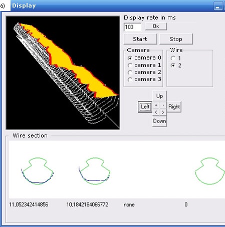
b
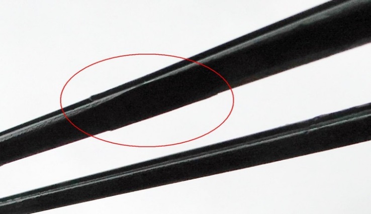
Fig. 5.
Reconstructed 3-D model of the worn-out section
of the OW (a)
and a photograph of this place (b)
The second
important aspect of the WEAR system modernization is the need to
obtain full-frame illuminated images of the CN elements at a high
speed for continuous scanning of objects of interest.
Based on the optical characteristics of
the lenses, the frame resolution and the distance at which the
cameras are located relative to the measured objects, the field
of view along the OW is Ɩ
= 37 mm. The maximum speed at which the WEAR system operates is ʋ =
72 km/h. The maximum time Ƭ
of receiving one frame, at which continuous scanning of the CN
is provided, is determined by the expression Ƭ
= c ∙
(Ɩ / ʋ),
where c =
0.0036 is the reduction coefficient of values to the SI system.
With the
given values Ɩ
and ʋ Ƭ
= 0.00185 s, which corresponds to the frequency of obtaining frames
ƒ = 541 fps.
The required
bandwidth of the channel C
for transmitting only an uncompressed image for a frame with a
resolution r
and a bitness of
one pixel n
is determined by the following expression: C
= r ∙ n ∙ ƒ.
With r
= 1 280 ∙ 128
and n
= 10
С
= 846 Mb/s.
Test
results of the WEAR system. The
automated system for measuring the wear of the
overhead wire installed on the LTCN
was tested along the 1 and 2 station track in variable cloud
conditions at a temperature of +28°C. A double contact wire
MF-100 is suspended within the test section. Automated measurements
were carried out at a measuring car speed of 37 km/h.
Manual wear
measurements were taken between the 69th and 71st supports along the
first station track. For accurate synchronization of measurements,
manual measurements were carried out next to the dropper and
pull-off clips, since such places can be easily identified using the
measurement data from the WEAR system. The measurements results are
given in Table 1.
It was found
that at the points being checked, the difference between the
automated measurements of the WEAR system and manual measurements of
the residual height does not exceed 0.26 mm.
Table
1
Results
of manual and automated
measurements
of OW wear along the
first station track
|
Distance
from support, cm
|
Manual
measurements,
mm
|
Wear
system measurement,
mm
|
Error,
mm
|
|
left
|
right
|
left
|
right
|
left
|
right
|
|
0
|
10.47
|
8.1
|
10.3
|
8.35
|
0.17
|
–0.25
|
|
075
|
9.57
|
9.49
|
9.5
|
9.29
|
0.07
|
0.2
|
|
150
|
10.13
|
9.57
|
10.16
|
9.54
|
–0.03
|
0.03
|
|
850
|
9.45
|
8.92
|
9.8
|
8.9
|
–0.35
|
0.02
|
|
1
875
|
9.36
|
9.1
|
9.3
|
8.98
|
0.06
|
0.12
|
|
2
875
|
8.5
|
9.38
|
8.65
|
9.05
|
–0.15
|
0.23
|
|
3
745
|
8.17
|
8.75
|
8.25
|
8.9
|
–0.08
|
–0.15
|
|
4
025
|
9.8
|
8.71
|
9.5
|
8.76
|
0.2
|
–0.05
|
|
4
085
|
9.24
|
8.71
|
9.7
|
8.7
|
–0.26
|
0.01
|
|
4
875
|
9
|
8.93
|
9.12
|
8.93
|
–0.12
|
0.11
|
|
5
850
|
9.8
|
9.35
|
9.5
|
9.2
|
0.24
|
0.23
|
|
6
000
|
9.37
|
9.67
|
9.2
|
9.5
|
0.16
|
0.26
|
|
6
075
|
9.2
|
9.76
|
9
|
9.61
|
0.25
|
0.15
|
During the
test drive on the second station track, several places were found
where, due to lateral wear of the overhead wire, the wear area
reached the clamp itself, as a result of which the bite wear began
(Fig. 5).
The
difference between manual and automatic measurements (Table 2) does
not exceed 0.33 mm in the residual wire height, except for the
reference
point at the
mark of 4 473 cm (right wire), where there is strong lateral
wear of the wire and an error could be made during manual
measurements.
Table
2
Results
of manual and automated measurements
of OW
wear along the second station track
|
Distance
from support, cm
|
Manual
measurements,
mm
|
Wear
system measurement,
mm
|
Error,
mm
|
|
left
|
right
|
left
|
right
|
left
|
right
|
|
0
|
11.5
|
11.5
|
11.4
|
11.3
|
0.1
|
0.2
|
|
25
|
9.25
|
10.4
|
9.11
|
10.43
|
0.14
|
–0.03
|
|
1
075
|
9.27
|
11.2
|
9.04
|
10.63
|
0.23
|
0.57
|
|
1
174
|
9.27
|
11.75
|
9.35
|
11.7
|
–0.08
|
0.05
|
|
1
211
|
9.38
|
11.65
|
9.19
|
11.63
|
0.19
|
0.02
|
|
1
982
|
9.75
|
10.95
|
9.78
|
10.88
|
–0.03
|
0.07
|
|
2
767
|
9.45
|
10.12
|
9.89
|
9.855
|
–0.24
|
0.265
|
|
2
839
|
10.1
|
10.15
|
10.03
|
10.01
|
0.07
|
0.14
|
|
3
557
|
10.45
|
11.55
|
10.37
|
11.7
|
0.08
|
–0.15
|
|
4
390
|
11
|
11.15
|
10.73
|
10.94
|
0.27
|
0.21
|
|
4
408
|
9.32
|
11.25
|
8.9
|
11.05
|
0.32
|
0.2
|
|
4
420
|
11
|
11.05
|
10.7
|
10.75
|
0.3
|
0.3
|
|
4
446
|
11.65
|
11.15
|
11.32
|
10.85
|
0.33
|
0.3
|
|
4
473
|
11.27
|
11.16
|
11.1
|
10.35
|
0.17
|
0.81
|
Originality
and practical value
The
theoretical maximum permissible, from the point of view of the
contact network operation, wear control error of the overhead wire
and other components of the electric traction network has been
determined. A method for increasing the resolution capability of a
stereo television system and an adaptive lighting system is
proposed, which consists in preliminary image transformation and
expansion of the dynamic range of image measurement.
The quality
of diagnostics of the contact network in difficult conditions for
video surveillance has been improved. A camera with a built-in image
compression module without loss of its performance has been
proposed, which allows capturing and transmitting full-frame images
to a computer complex for the application of new diagnostic
algorithms for the components of the contact network of electrified
railways and urban electric transport.
Conclusions
To reduce the
wear of the overhead wire and current collector plates, to ensure
reliable and economical current collection in the process of
transportation by electric transport, high-quality diagnostics of
the electric traction network is required. The proposed video system
has the following speed characteristics: obtaining a JPEG image with
a compression ratio of k>
= 10 and a resolution of 1 280 x 128 at a speed of 976 fps. In this
case, the required maximum speed of compressed data transfer does
not exceed 85 Mb/s. The system is equipped with fast-acting LED
backlighting, which makes it possible to obtain a continuous
illuminated image of the CN elements in real time. Thus, the
improvement of the WEAR laser fast-acting system can significantly
increase the reliability and reduce the detection time of emerging
OW malfunctions and other CN components.
LIST OF
REFERENCE LINKS
Аналіз
роботи господарства електрифікації
та електропостачання в 2011 році.
Київ : «Укрзалізниця»,
Головне Управління Електрифікації та
Електропостачання, 2012. 323 с.
Аналіз
роботи господарства електропостачання
в 2015 році. Київ :
ПАТ «Українська залізниця»,
Департамент Електропостачання, 2016. 148
с.
Вологин
В. А. Взаимодействие
токоприемников и контактной сети.
Москва : Интекст, 2006. 256 с.
Доманський В. Т.,
Переверзєв К. В. Концепція технічного
обслуговування пристроїв електропостачання
залізниць за станом на базі їх діагностики
і моніторингу. Українська
залізниця. 2019. №
3 (69).
С. 9–13.
Доманський І. В.
Основи енергоефективності
електричних систем з тяговими
навантаженнями :
монографія. НТУ «ХПІ».
Харків : вид-во ТОВ «Центр
інформації транспорту України», 2016.
224 с.
Корниенко
В. В., Котельников А. В., Доманский В. Т.
Электрификация железных дорог. Мировые
тенденции и перспективы (Аналитический
обзор) : монография. Киев : Транспорт
Украины, 2004. 196 с.
Переверзев К. В.
Современные методы и средства диагностики
контактных сетей электрифицированных
железных дорог. Українська залізниця.
2019. № 6 (72). С. 23–27.
Столбов П. В.
Высокоскоростная специализированная
матричная камера с расширенным
динамическим диапазоном и сжатием
изображения. Материалы 14-ой международной
конференции «Телевидение : передача и
обработка изображений» (Санкт-Петербург,
27–28 июня 2017 г.). Санкт-Петербург, 2017. С.
54–57.
Хворост
М. В., Доманський І. В.,
Васенко В. О. Ресурсозберігаючі
технології експлуатації контактної
мережі за станом для міського
електротранспорту. Світлотехніка
та електроенергетика.
2020. Вип. 58, № 02. С. 3–9. DOI:
10.33042/2079-424X-2020-2-58-3-9
Шевяков С. М.,
Сиротинин В. И., Сафин В. Г,
Воронин А. В. Видеоизмерительные
системы диагностики контактной сети.
Евразия Вести. 2017. № 11.
С. 23.
Demydov
O., Liubarskyi B., Domanskyi
V, Glebova
M., Iakunin D., Tyshchenko A.
Determination of optimal parameters of the
pulse width modulation of the 4qs transducer for electriс
rolling stock. Eastern-European Journal
of Enterprise Technologies. 2018. Vol.
5. Iss. 5 (95). P. 29–38. DOI:
10.15587/1729-4061.2018.143789
Domanskyi I.,
Kozlova О. Development prospects of external power supply
electrical networks of traction substations. Series
: Engineering Science and Architecture. 2020.
Vol. 1. Iss. 154. P. 8–15.
DOI:
10.33042/2522-1809-2020-1-154-8-15
Information
technology – digital compression and coding of continuous-tone
still images – Requirements and guidelines. URL:
https://www.w3.org/graphics/jpeg/itu-t81.pdf (дата
звернення: 05.01.2021)
Kiessling F.,
Puschmann R., Schmieder A., Schneider E. Contact
Lines for Electric Railways : Planning, De-sign, Implementation,
Maintenance, 3rd Edition. Wiley
Publishers, 2017. 994 p.
Sarnes B.
Измерительная система для определения
положения и износа контактного провода.
Elektrische Bahnen.
2001. №
12.
C. 490–495.
Schmidt H.,
Schmieder A. Current
collection for high-speed transport.
Elektrische Bahnen. 2005.
№ 4.
P. 231–236.
Sohei
Y., Toshihide
K., Hiroshi
Y. Utilization
of Data
Obtained Using
Power Equipment
Monitoring
System Equipped
to Series
E235 Rolling
Stock. JR
EAST
Technical
Review.
2016. № 34. P.
33–36.
І. В.
Доманський1*,
В. О. ВАСЕНКО2
1*Каф.
«Електричний транспорт», Харківський
національний університет
міського
господарства імені О. М. Бекетова, вул.
Маршала Бажанова, 17,
Харків, Україна,
61002, тел. +38 (056) 736 24 80,
ел. пошта
ilya.domanskiy@gmail.com, ORCID 0000-0001-8819-410X
2Комунальне
підприємство «Міськелектротранссервіс»,
вул. Актюбінська, 24,
Харків,
Україна, 61001, тел. +38 (057)
737 96 58,
ел. пошта vladvasenko2021@gmail.com,
ORCID 0000-0001-8613-973X
Удосконалення
відеовимірювальних
систем діагностики
електротягової мережі
Мета.
Основною метою статті є системний аналіз
стану електротягових мереж, а також
методів комплексної діагностики
контактної мережі (КМ) з рухомого
вагона-лабораторії для підвищення
роздільної здатності систем контролю
якості взаємодії контактної мережі і
струмоприймачів. Методика.
Поставлену задачу вирішено шляхом
теоретичного аналізу та експериментальних
досліджень параметрів струмозняття,
узагальненої моделі пристрою контролю
зносу контактного проводу (КП) та його
функціональних вузлів із метою визначення
факторів, що впливають на похибку
контролю, а також розробки методів, що
знижують зазначену похибку. При цьому
використано апарат факторного аналізу,
теорію оптико-електронних схем і
методи статистичної обробки інформації.
Результати.
Запропоновано інноваційні підходи та
якісно нові діагностичні засоби, що
дозволяють розширити функціональні
можливості вагонів-лабораторій
випробування контактної мережі для
підприємств електропостачання
електрифікованих залізниць, промислового
й міського електротранспорту.
Розроблено апаратні та програмні засоби
для вдосконалення системи вимірювання
параметрів контактного проводу та інших
компонентів контактної мережі. Наукова
новизна. Визначене
теоретичну максимально допустиму, із
точки зору експлуатації контактної
мережі, похибку контролю зносу контактного
проводу та інших компонентів електротягової
мережі. Запропоновано метод підвищення
роздільної здатності стереотелевізійної
системи й адаптивної системи освітлення,
що полягає в попередній трансформації
зображення й розширенні динамічного
діапазону вимірювання зображення.
Запропоновано шляхи впровадження
високошвидкісного алгоритму стиснення
реального часу й застосування
світлодіодного підсвічування. Практична
значимість. Підвищено
якість діагностики контактної мережі
в складних для відеоспостереження
умовах. Запропоновано камеру із вбудованим
модулем стиснення зображення без втрати
її швидкодії, що дозволяє захоплювати
й передавати в обчислювальний комплекс
повнокадрові зображення для застосування
нових алгоритмів діагностики компонентів
контактної мережі. Запропоновано
модернізовані відеовимірювальні системи
вимірювання зносу контактного проводу,
контролю заземлення опор контактної
мережі, а також елементів колійного
господарства, розташованого в зоні
видимості спеціалізованих камер, які
забезпечують працездатність систем у
будь-який час доби на швидкостях до 160
км/год. Для захисту камер реалізовано
підсистему повітряної завіси.
Ключові
слова: системи діагностики;
контактна мережа (КМ); знос контактного
проводу (КП); оптичні методи вимірювань
REFERENCES
Analiz
roboty hospodarstva elektryfikatsiyi ta elektropostachannya v 2011
rotsi. (2012). Kiev: «Ukrzaliznytsya»,
Holovne Upravlinnya Elektryfikatsiyi ta Elektropostachannya. (in
Ukrainian)
Analiz
roboty hospodarstva elektropostachannya v 2015 rotsi.
(2016). Kiev: PAT «Ukrayins'ka zaliznytsya», Departament
Elektropostachannya. (in Ukrainian)
Vologin,
V. A. (2006). Vzaimodeystvie
tokopriemnikov i kontaktnoy seti.
Mosсow:
Intekst. (in Russian)
Domanskyy,
V. T., & Pereverzyev, K. V. (2019). Kontseptsiya tekhnichnoho
obsluhovuvannya prystroyiv elektropostachannya zaliznyts za stanom
na bazi yikh diahnostyky i monitorynhu. Ukrainian
Railway, 3(69),
9-13. (in Ukrainian)
Domanskyy,
I. V. (2016). Osnovy enerhoefektyvnosti
elektrychnykh system z tyahovymy navantazhennyamy:
monohrafiya. NTU «KhPI». Kharkiv: vydavnytstvo TOV «Tsentr
informatsiyi transportu Ukrayiny». (in Ukrainian)
Kornienko, V. V.,
Kotelnikov, A. V., & Domanskiy, V. T.
(2004). Elektrifikatsiya zheleznykh
dorog. Mirovye tendentsii i perspektivy (Analiticheskiy obzor):
monografiya. Kiev : Transport Ukrainy. (in Russian)
Pereverzev, K. V.
(2019). Sovremennye metody i sredstva diagnostiki kontaktnykh setey
elektrifitsirovannykh zheleznykh dorog. Ukrainian
Railway, 6(72),
23-27. (in Russian)
Stolbov,
P. V. (2017). Vysokoskorostnaya spetsializirovannaya
matrichnaya kamera s rasshirennym dinamicheskim diapazonom i
szhatiem izobrazheniya. Materialy 14-oy mezhdunarodnoy konferentsii
«Television: images broadcasting &
processing» (pp. 54-57).
St. Petersburg, Russia. (in Russian)
Khvorost,
M., Domanskiy, I., & Vasenko, V. (2020). Resource-saving
technologies of operation of a contact network on the state for city
electric transport. Lighting
Engineering & Power Engineering, 2(58),
3-9.
DOI: 10.33042/2079-424X-2020-2-58-3-9.
(in Ukrainian)
Shevyakov,
S. M., Sirotinin, V. I., Safin, V. G., & Voronin, A. V. (2017).
Videoizmeritelnye sistemy diagnostiki kontaktnoy seti. Yevraziya
Vesti, 11, 23. (in Russian)
Demydov,
О., Liubarskyi, B., Domanskyi, V., Glebova, M., Iakunin, D., &
Tyshchenko, A. (2018). Determination of optimal parameters of the
pulse width modulation of the 4qs transducer for electriс rolling
stock. Eastern-European Journal of
Enterprise Technologies, 5(5(95)),
29-38. DOI: 10.15587/1729-4061.2018.143789
(in English)
Domanskyi,
I., & Kozlova, О. (2020). Development prospects of external
power supply electrical networks of traction substations. Series:
Engineering Science and Architecture, 1(154),
8-15.
DOI:
10.33042/2522-1809-2020-1-154-8-15
(in English)
Information
technology-digital compression and coding of continuous-tone still
images-Requirements and guidelines. Retrieved from
https://www.w3.org/graphics/jpeg/itu-t81.pdf (in English)
Kiessling,
F., Puschmann, R., Schmieder, A., & Schneider, E. (2017).
Contact Lines for Electric
Railways:Planning, Design, Implementation, Maintenance, 3rd Edition.
Wiley Publishers. (in English)
Sarnes, B.
(2001). Izmeritelnaya sistema dlya opredeleniya polozheniya i iznosa
kontaktnogo provoda. Elektrische
Bahnen, 12,
490-495. (in Russian)
Schmidt, H.,
& Schmieder A. (2005). Current collection for high-speed
transport. Elektrische Bahnen,
4,
231-236. (in English)
Sohei,
Y., Toshihide,
K., &
Hiroshi, Y.
(2016). Utilization
of Data
Obtained Using
Power Equipment
Monitoring
System Equipped
to Series
E235 Rolling
Stock. JR
EAST
Technical
Review,
34,
33-36.
(in English)
Received:
Oct. 02, 2020
Accepted:
Feb. 02, 2021