ISSN
2307–3489 (Print), ІSSN
2307–6666
(Online)
Наука
та прогрес транспорту. Вісник
Дніпропетровського
національного університету залізничного
транспорту, 2019, №
(
)
ІНФОРМАЦІЙНО-КОМУНІКАЦІЙНІ
ТЕХНОЛОГІЇ
ІНФОРМАЦІЙНО-КОМУНІКАЦІЙНІ
ТЕХНОЛОГІЇ
UDC
004.7.032.26:656.222.3
V. M. PAKHOMOVA1*,
Y. S. MANDYBURA2*
1*Dep.
«Electronic Computing Machines», Dnipro National University of
Railway Transport named after Academician V. Lazaryan, Lazaryana
St., 2, 49010, Dnipro, Ukraine, tel. +38 (056) 373 15 89, e-mail
viknikpakh@gmail.com, ORCID 0000-0002-0022-099X
2*Dep.
«Electronic Computing Machines», Dnipro National University of
Railway Transport named after Academician V. Lazaryan, Lazaryana
St., 2, 49010, Dnipro, Ukraine, tel. +38 (056) 373 15 89, e-mail
mandybura1994@gmail.com,ORCID
0000-0002-7134-9416
OPTIMAL
ROUTE DEFINITION IN THE RAILWAY
INFORMATION NETWORK USING NEURAL-FUZZY
MODELS
Purpose. Modern
algorithms for choosing the shortest route, for example, the
Bellman-Ford and Dijkstra algorithms, which are currently widely used
in existing routing protocols (RIP, OSPF), do not always lead to an
effective result. Therefore, there is a need to study the possibility
of organizing routing in in the railway network of information and
telecommunication system (ITS) using the methods of artificial
intelligence. Methodology.
On the basis of the simulation model created in the OPNET modeling
system a fragment of the ITS railway network was considered and the
following samples were formed: training, testing, and control one.
For modeling a neural-fuzzy network (hybrid system) in the the MatLAB
system the following parameters are input: packet length (three term
sets), traffic intensity (five term sets), and the number of
intermediate routers that make up the route (four term sets). As the
resulting characteristic, the time spent by the packet in the routers
along its route in the ITS network (four term sets) was taken. On the
basis of a certain time of packet residence in the routers and queue
delays on the routers making up different paths (with the same number
of the routers) the optimal route was determined. Findings.
For the railway ITS fragment
under consideration, a forecast was made of the packet residence time
in the routers along its route based on the neural-fuzzy network
created in the MatLAB system. The authors conducted the study of the
average error of the neural-fuzzy network`s training with various
membership functions and according to the different methods of
training optimization. It was found that the smallest value of the
average learning error is provided by the neuro-fuzzy network
configuration 3–12–60–60–1 when using the symmetric Gaussian
membership function according to the hybrid optimization method.
Originality.
According to the RIP and OSPF
scenarios, the following characteristics were obtained on the
simulation model created in the OPNET simulation system: average
server load, average packet processing time by the router, average
waiting time for packets in the queue, average number of lost
packets, and network convergence time. It was determined that the
best results are achieved by the simulation network model according
to the OSPF scenario. The proposed integrated routing system in the
ITS network of railway transport, which is based on the neural-fuzzy
networks created, determines the optimal route in the network faster
than the existing OSPF routing protocol. Practical
value. An integrated routing
system in the ITS system of railway transport will make it possible
to determine the optimal route in the network with the same number of
the routers that make up the packet path in real time.
Keywords: routing; OSPF protocol; simulation model; hybrid
system; term; membership function; sample; error
Introduction
At present,
various scientists have been searching for a solution of the routing
problem in the computer networks based on the use of neural networks
[1, 3–4, 6, 14]. The first such attempt was made by Hopfield to
solve the traveling salesman problem [11]. Pavlenko M. A. analyzed
the possibilities of some neural networks: multilayer perceptron,
Hopfield network, RBF network for organizing routing of five routers
[6]. It has been established that the most promising way to solve
the routing problem is the Hopfield`s network, which is able to
operate in real time, but in the case of using it one needs to
conduct additional studies of the transfer functions of neurons and
the energy function of the neural network [4, 8, 11, 18].
In turn,
fuzzy neural networks (hybrid systems) are designed to combine the
benefits of neural networks and fuzzy inference systems [13, 17].
This makes it possible to develop and submit the systems models in
the form of fuzzy product rules to construct which the capabilities
of the neural networks are used. For example, the
Adaptive–Network–Based Fuzzy Inference
System (ANFIS) implemented in the MatLAB
Fuzzy Logic Toolbox application [9–10]. In the work [2], in
particular, Kovalenko T. A. determined the route in the computer
network based on the neural fuzzy network, to the input of which the
following parameters are supplied: number of transitions, data
transmission speed; as a resultant characteristic the time of the
packet residence in the route was taken. But it is appropriate for
the railway ITS network to consider a change in the traffic
intensity rather than a data transmission speed that requires the
construction of a neural network of another structure. In addition,
based on the estimated packet transmission time in the network, it
is advisable to determine the route itself, provided the same number
of routers on the paths of the packet, which also requires the
creation of additional neural network.
Previously,
the authors of the works [7, 15–16, 20] have already presented the
results of studies of the use of intellectual means in the railway
ITS network: Hopfield network and multi-layer neural network, ant
and genetic methods. In addition, the possibility of using the RIP
protocol in the Prydniprovska Railway network on a software model
was investigated. But nowadays, new modeling systems have emerged
that allow us to create simulation models of networks and conduct
research on them. Among them, the OPNET Modeler system [5, 12],
which combines analytical methods and simulation tools.
Purpose
In our work,
we envisage for the railway ITS network to develop a methodology for
determining the optimal route based on the use of fuzzy neural
networks. For their modeling to generate samples on a simulation
model of the railway ITS network fragment created in the OPNET
Modeler system.
Methodology
Problem
statement.
Today, the railway transport ITS network, the fragment of which is
presented in Fig. 1, is being constructed based on an optical
transport network. Conceptually, to construct a single data network
of Ukrzaliznytsia, Cisco network equipment was selected, which is a
single hardware and software complex. At the present stage in the
railway ITS network, the router performs OSPF (Open Shortest Path
First) pro-tocol, as it is a common standard supported by various
network equipment manufacturers and avoids closed loops during
development of the data transmission networks at the railway
transport of Ukraine.
Given that
the packet transmission time on the network channel is much shorter,
it is only advisable to consider the packet residence time on the
routers that make up its path in the ITS network. Given that the
packets are received by the router according to the Poisson law and
the distribution of processing time is exponential, we have the
М/М/1model.
Then the packet residence time on the router is calculated in the
following way:
 ,
(1)
,
(1)
where
 – package residence
time on
the i-th
router, μs;
– package residence
time on
the i-th
router, μs;
 – packet waiting time in the queue on the i-th
router, μs;
– packet waiting time in the queue on the i-th
router, μs;
 – packet processing time by the i-th router, μs.
In turn, the
processing time of packet by the i-th
router can be calculated by the well-known formula:
 ,
(2)
,
(2)
where
 – packet length, byte; V
– the rate of data staging by the router, Mbps (in particular for
Fast Ethernet 100 Mbps).
– packet length, byte; V
– the rate of data staging by the router, Mbps (in particular for
Fast Ethernet 100 Mbps).
The number
of packets processed by the i-th
router will be:
 ,
(3)
,
(3)
where
 –
the intensity of packets receipt to the i-th
router, packet/s.
–
the intensity of packets receipt to the i-th
router, packet/s.
Then the
calculation of the packet waiting time in the queue on the i-th
router is calculated by the following formula:
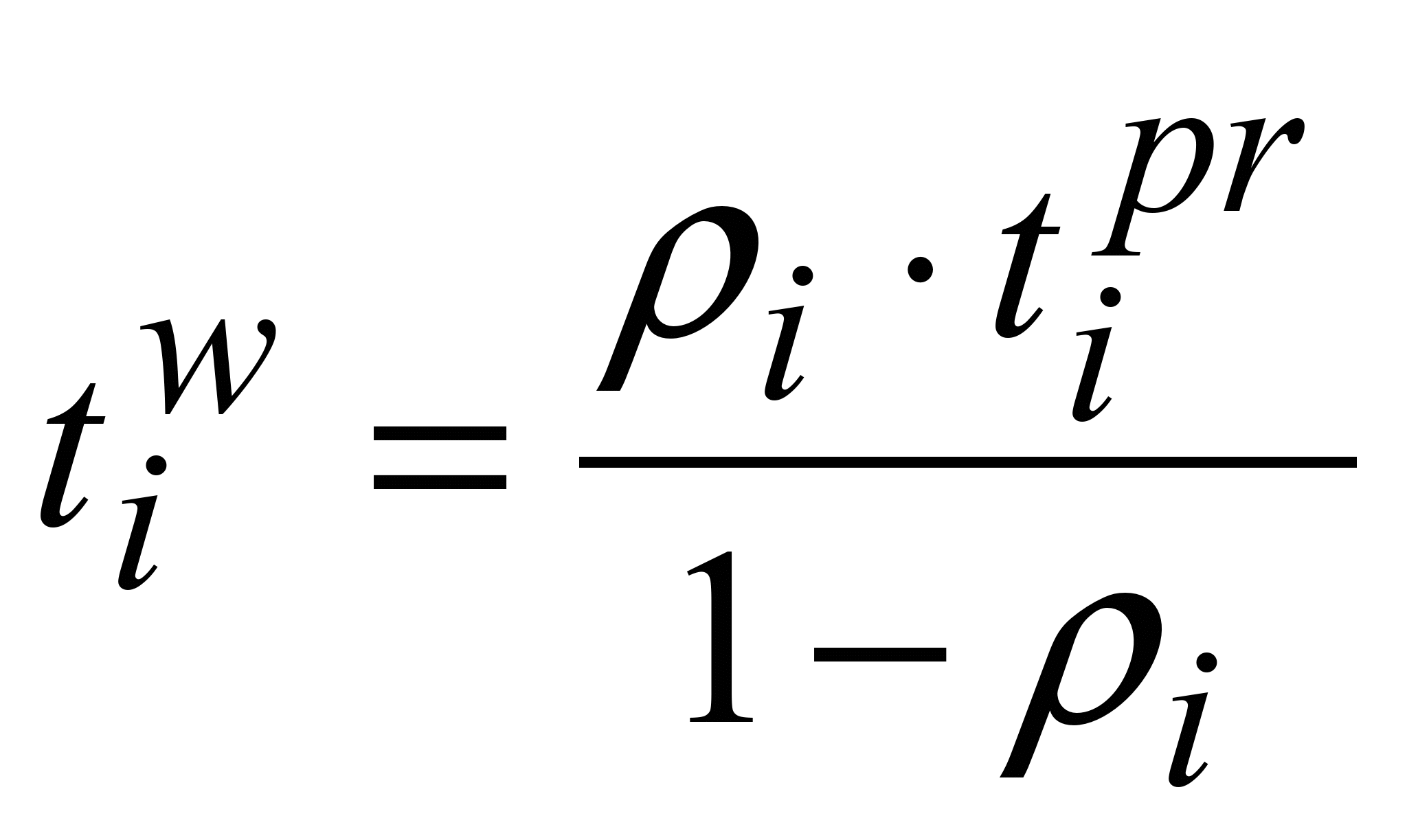 .
(4)
.
(4)
It is necessary to determine
the optimal route of packet in the railway ITS network provided
that:
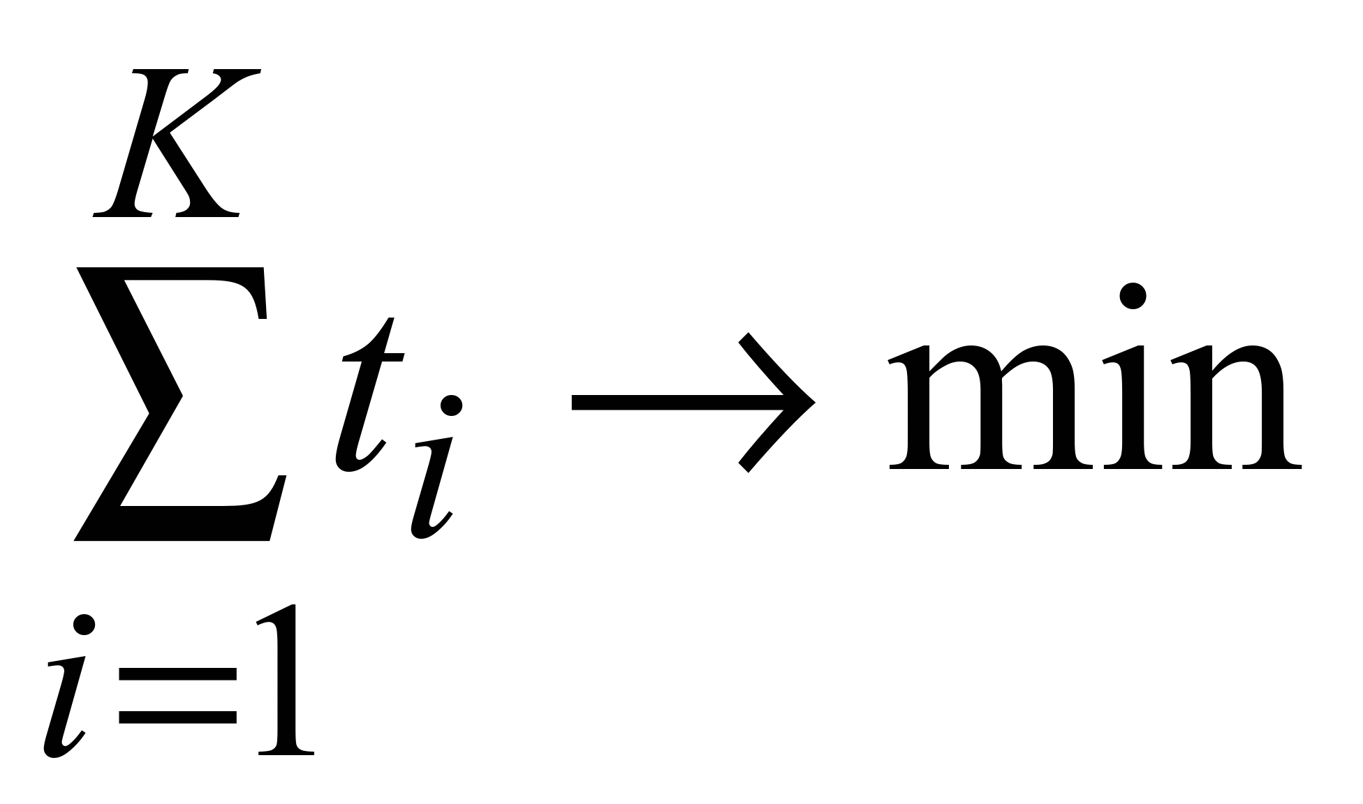 ,
(5)
,
(5)
where
K
– is the number of intermediate routers that make up the packet
path.
Creating
a simulation model. In
the OPNET Modeler simulation system a simulation model of the ITS
railway network fragment was created, the structure of which is
presented in Fig. 2, according to the structure of the ITS network
(see Fig. 1).
Two
scenarios have been created on the Fast Ethernet simulation model at
the ITS of Prydniprovska Railway: RIP and OSPF protocol. The study
(within five minutes) of the following characteristics was
performed: average load of the server located in Kyiv; average
packet processing time by the router in Dnipro; average waiting time
for packets in the queue (Dnipro–Synelnykove section); average
number of packets lost with the following parameters: packet length
is 6000 bits, traffic intensity is 10 packets/sec. Some
characteristics obtained (from 2 min 00 sec to 3 min 00 sec) on the
simulation model of the network are shown in Fig. 3.
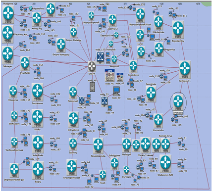
Fig. 2. Simulation
model in the OPNET Modeler:
 – router;
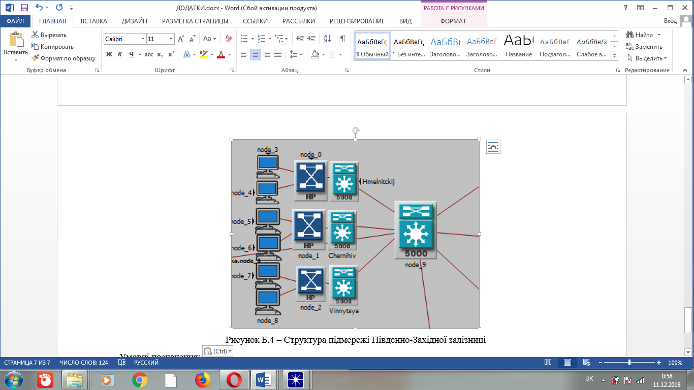 – switch;
– workstation
– switch;
– workstation
Fig. 3 shows
that the worst results are obtained by the network simulation model
according to the RIP scenario: server load increases rapidly (on
average, about by 3 times per minute); packet processing time by the
router takes much longer (approximately by 0.5 times per minute);
the packet waiting time in the queue is always greater (about by 1.6
times per minute); packet losses increase rapidly (on average by 3.5
times per minute); the network convergence time is almost twice as
large. As an example, the average waiting time of packets in the
queue and the average number of packets lost on the router are
shown, Fig. 3. Regardless of the routing protocol (RIP or OSPF): the
longer the waiting time for packets in the queue (Fig. 3, a),
the higher the number of lost packets (Fig. 3, b).
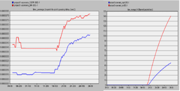
а
б
Fig.
3. The experiment results on a simulation model:
а
– the average waiting time for packets in a queue;
b–
the average number of packets lost on the router
Determining
the packet residence time on the routers based on the use of Neural
Fuzzy Network (NN1).
The
following variables are used as the input parameters:
 – packet
length (LМ,
LС,
L);
– packet
length (LМ,
LС,
L);
 – traffic
intensity (
– traffic
intensity ( ,
, ,
,
 ,
,
 ,
,
 );
);
 –
number
of transitions (number of intermediate routers that make up the
packet route) (K1,
K2,
K3,
K4).
The packet residence time in the routers on the route of its
transmission in the ITS network (T1,
T2,
T3,
T4)
is taken as the resultant characteristic y.
The values of the term sets used for linguistic evaluation of input
and output variables are summarized in Table 1.
–
number
of transitions (number of intermediate routers that make up the
packet route) (K1,
K2,
K3,
K4).
The packet residence time in the routers on the route of its
transmission in the ITS network (T1,
T2,
T3,
T4)
is taken as the resultant characteristic y.
The values of the term sets used for linguistic evaluation of input
and output variables are summarized in Table 1.
Table
1
Linguistic
evaluation of input and output variables for NN1
|
Input
variables
|
Output variable
|
|
Packet
length,
bytes
|
Traffic
intensity,
packet/s
|
Number
of transitions
|
Packet
residence time on the routers on the route, μs
|
|
LМ:
70 – 500
LС:
501 – 1 000
L:
1 001 – 1 500
|
:
10 – 200
:
201 – 400
:
401 – 600
:
601 – 800
:
801 – 1 000
|
K1:
1
K2:
2
K3:
3
K4:
4
|
T1:
5,6 – 140
T2:
141 – 275
T3:
276 – 410
T4:
411 – 545
|
The number
of fuzzy product rules depends on the number of input variables and
the number of terms and is
 rules.
The rule base fragment is presented below:
rules.
The rule base fragment is presented below:
if
=
LМ
І
=
І
=
K1,
then
у
=
T1;
if
=
LМ
І
=
І
=
K2,
then
у
=
T3;
if
=
LМ
І
=
І
= K3,
then
у
=
T1;
if
=
LМ
І
=
І
=
K4,
then
у
=
T4;
if
=
LМ
І
=
І
=
K1,
then
у
=
T1;
if
=
LМ
І
=
І
=
K2,
then
у
=
T3;
if
=
LМ
І
=
І
=
K3,
then
у
=
T1;
if
=
LМ
І
=
І
=
K4,
then
у
=
T4;
if
=
LМ
І
=
І
=
K1,
then
у
=
T1.
The
structure of the corresponding NN1 is shown in Fig. 4. Layer 1
contains neurons that represent membership functions of the input
fuzzy variables and perform the operation of fuzzification (making
fuzzy) of the input data. Layer 2 contains neurons that store the
correct values for the rules that make up the knowledge base created
by the model's training; these neurons may contain any variant of
the realization of the t-norm
operation, which is a fuzzy analogue of "AND"
(logical operation "AND"). Neurons of the layer 3 contain
the results of calculations of rules, taking into account the weight
of each rule. Neurons of the layer 4 contain the final results of
the rules` calculations, which are grouped into fuzzy classes. Layer
5 contains only one neuron that calculates the final model output by
performing a defuzzification (making clear) by determining the
centers of fuzzy classes.
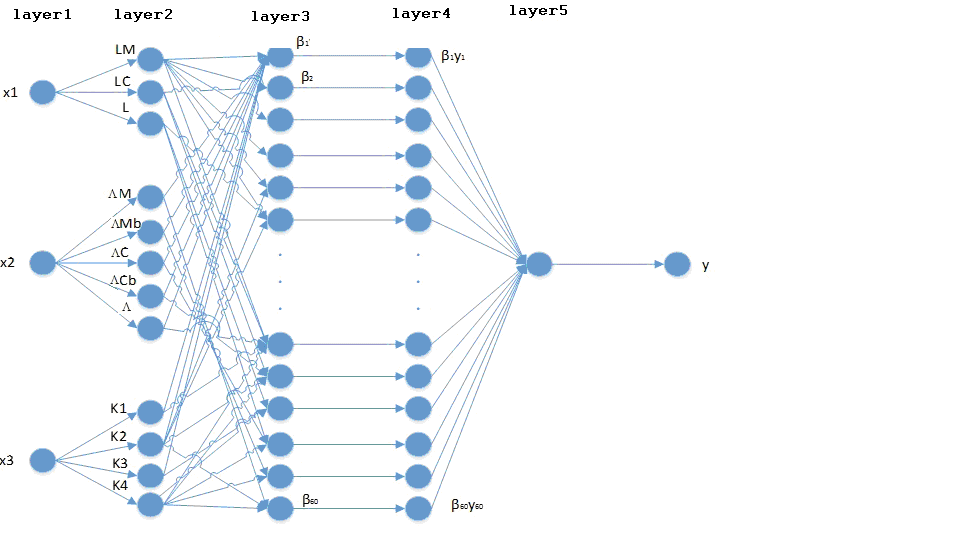
Fig.
4. NN1 structure
Formation
of samples for the NN1. The
following samples for the NN1 were formed: a training sample of 60
examples (a fragment of which is given in Table 2), a test sample of
24 examples and a control sample of 12 examples (Table 3).
Table
2
Fragment
of training sample for the NN1
|
Packet length,
bytes
|
Traffic
intensity,
packet/sec
|
Number
of transitions
|
Packet
time in the routers on the route, μs
|
Packet length,
bytes
|
Traffic intensity,
packet/sec
|
Number
of transitions
|
Package
time in the routers on the route, μs
|
|
70
|
10
|
1
|
5.6
|
70
|
1 000
|
1
|
5,6
|
|
500
|
10
|
1
|
40
|
500
|
1 000
|
1
|
42
|
|
1 000
|
10
|
1
|
80
|
1 000
|
1 000
|
1
|
87
|
|
1 500
|
10
|
1
|
120
|
1 500
|
1 000
|
1
|
136
|
|
70
|
10
|
2
|
11.2
|
70
|
1 000
|
2
|
11
|
|
500
|
10
|
2
|
80
|
500
|
1 000
|
2
|
83
|
|
1 000
|
10
|
2
|
160
|
1 000
|
1 000
|
2
|
174
|
|
1 500
|
10
|
2
|
360
|
1 500
|
1 000
|
2
|
273
|
|
70
|
10
|
3
|
16.8
|
70
|
1 000
|
3
|
17
|
|
500
|
10
|
3
|
120
|
500
|
1 000
|
3
|
125
|
|
1 000
|
10
|
3
|
240
|
1 000
|
1 000
|
3
|
261
|
|
1 500
|
10
|
3
|
360
|
1 500
|
1 000
|
3
|
409
|
|
70
|
10
|
4
|
22.4
|
70
|
1 000
|
4
|
23
|
|
500
|
10
|
4
|
160
|
500
|
1 000
|
4
|
167
|
|
1 000
|
10
|
4
|
320
|
1 000
|
1 000
|
4
|
348
|
|
1 500
|
10
|
4
|
480
|
1 500
|
1 000
|
4
|
545
|
Table
3
Test
and control samples for the NN1
|
Test
sample
|
Control
sample
|
|
|
Packet length,
bytes
|
Traffic intensity,
packet/sec
|
Number
of transitions
|
Package
time in the routers on the route, μs
|
Packet length,
bytes
|
Traffic intensity,
packet/sec
|
Number
of transitions
|
Package
time in the routers on the route, μs
|
|
500
|
300
|
1
|
40
|
500
|
500
|
1
|
41
|
|
1 000
|
300
|
1
|
82
|
1 000
|
500
|
1
|
83
|
|
1 500
|
300
|
1
|
124
|
1 500
|
500
|
1
|
128
|
|
500
|
300
|
2
|
81
|
500
|
500
|
2
|
82
|
|
1 000
|
300
|
2
|
163
|
1 000
|
500
|
2
|
167
|
|
1 500
|
300
|
2
|
373
|
1 500
|
500
|
2
|
255
|
|
500
|
300
|
3
|
121
|
500
|
500
|
3
|
122
|
|
1 000
|
300
|
3
|
245
|
1 000
|
500
|
3
|
250
|
|
1 500
|
300
|
3
|
373
|
1 500
|
500
|
3
|
383
|
|
500
|
300
|
4
|
162
|
500
|
500
|
4
|
163
|
|
1 000
|
300
|
4
|
328
|
1 000
|
500
|
4
|
333
|
|
1 500
|
300
|
4
|
498
|
1 500
|
500
|
4
|
511
|
|
500
|
700
|
1
|
41
|
|
|
|
|
|
1 000
|
700
|
1
|
85
|
|
|
|
|
|
|
1 500
|
700
|
1
|
131
|
|
|
|
|
|
|
500
|
700
|
2
|
82
|
|
|
|
|
|
|
1 000
|
700
|
2
|
169
|
|
|
|
|
|
|
1 500
|
700
|
2
|
393
|
|
|
|
|
|
|
500
|
700
|
3
|
123
|
|
|
|
|
|
|
1 000
|
700
|
3
|
254
|
|
|
|
|
|
|
1 500
|
700
|
3
|
393
|
|
|
|
|
|
|
500
|
700
|
4
|
165
|
|
|
|
|
|
|
1 000
|
700
|
4
|
339
|
|
|
|
|
|
|
1 500
|
700
|
4
|
524
|
|
|
|
|
|
Training
and testing the NN1. The
Neural Networks Toolbox, which is a part of MatLAB, has more than
160 different functions that make it possible to create, train, and
research neural networks. In addition, the ANFIS for MatLAB supports
almost complete automation of the NN creation process, which allows
to construct the NN configuration 3–12–60–60–1,
using the Sugeno algorithm. 100 cycles (Epochs) are set for NN1
training; the error of the NN1 training according to the hybrid
method is
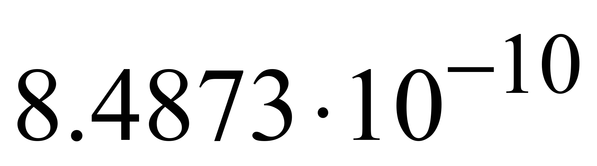 sec.
sec.
On
the network simulation model, constructed in the ORNET, with a
packet length of 550 bytes, traffic intensity of 10 packets/sec and
three transitions, the packet residence time on the routers in the
ITS railway transport network is 0.000132 sec. To test the
constructed NN1, let us run it with input data that are not in any
of the samples. The simulation is displayed in a graphical window
(Fig. 5), where the path of the logical inference by each rule,
the resultant fuzzy set are presented, and the deffuzzification
procedure is performed.
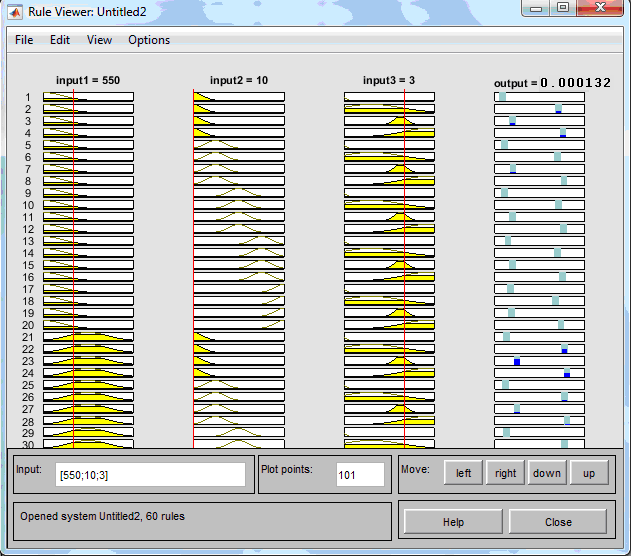
Fig. 5. System of fuzzy
output NN1
Each
rule of the knowledge base is represented as a sequence of
horizontally arranged curves. The resulting fuzzy set is shown in
the lower rectangle of the last column of the graphical window. In
the same rectangle, the red vertical line corresponds to the clear
value of the logical inference obtained from the deffuzzification.
According to the input data [550; 10; 3] the NN1 displays the packet
residence time on the routers according to the path of its
transmission, equal to 0.000132 s (Fig. 6). That is, NN1 is properly
constructed and trained.
Route
definition based on the use of a neural fuzzy network (NN2). The
following variables are used as input parameters:
–
is
the packet residence time on the routers according to the packet
transmission route (Tmin,
Tavg,
Tmax);
–
is the total
queue delay on the routers on the route A
(ZAmin, ZAma, ZAavg, ZAam, ZAmax);
– is the total
queue delay on the routers on the route В
(ZBmin,
ZBma,
ZBavg,
ZBam,
ZBmax)
;
y
–
is the optimal route: 1 (path A),
2 (path B).
All values are summarized in Table 4.
Table
4
Linguistic
evaluation of input and output variables for NN2
|
|
Input variables
|
|
|
Output
variable
|
|
Packet
residence time in the routers on the route, μs
|
Total
queue delay on the routers on the path А,
μs
|
Total
queue delay on the routers on the path В,
μs
|
Route
|
|
Tmin:
5,6 – 185;
Tavg:
186 – 365;
Tmax:
366 – 545
|
ZАmin:
0 – 13;
ZАma:
14 – 27;
ZАavg:
28 – 41;
ZАam:
42 – 55;
ZАmax:
56 – 70
|
ZАmin:
0 – 13;
ZАma:
14 – 27;
ZАavg:
28 – 41;
ZАam:
42 – 55;
ZАmax:
56 – 70
|
А:
1
В:
2
|
The number
of fuzzy product rules depends on the number of input variables and
the number of terms, this value is
 rules. The rule base fragment is given below:
if
=Tmin
І=ZАmin
І=ZВmin,
then
у=В;
if
=Tmin
І=ZАmin
І=ZВma,
then
у=B;
if
=Tmin
І=ZАmin
І=ZВavg,
then
у=B;
if
=Tmin
І=ZАmin
І=ZВam,
then
у=B;
if
=Tmin
І=ZАmin
І=ZВmax,
then
у=B;
if
=Tmin
І=ZАma
І=ZВmin,
then
у=A;
if
=Tmin
І=ZАma
І=ZВma,
then
у=B;
if
=Tmin
І=ZАma
І=ZВavg,
then
у=B;
if
=Tmin
І=ZАma
І=ZВam,
then
у=B.
The
structure of the corresponding NN2 is shown in Fig. 6.
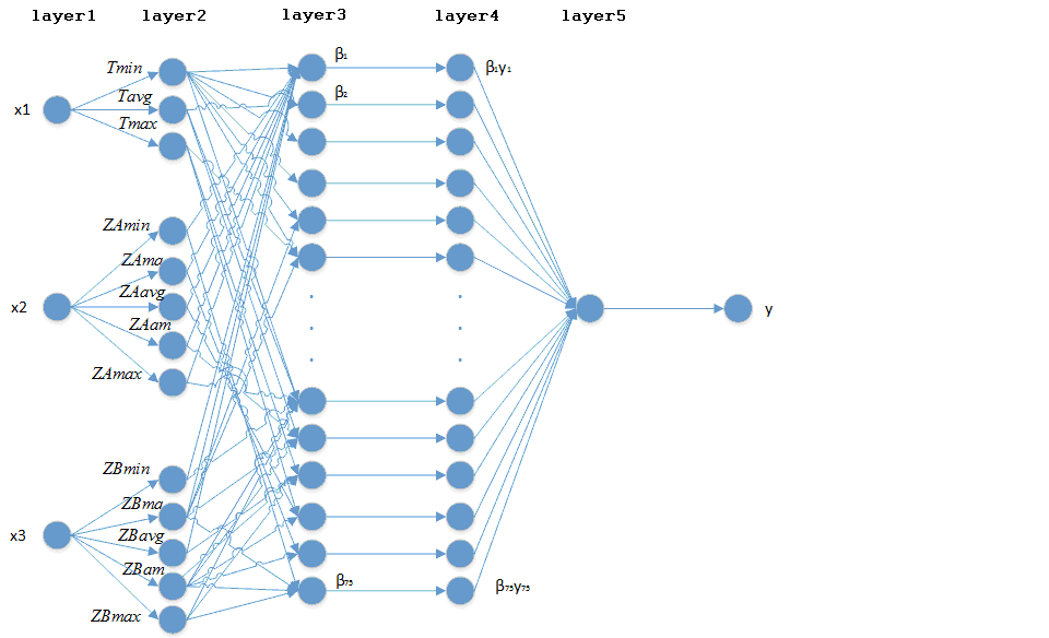
Fig. 6. NFN2 structure
Formation
of the samples NN2.
The
following samples were formed: a training sample of 75 examples, a
test sample of 20 examples and a control of 10 examples (Table 5).
Table
5
Samples
fragments for NN2
|
Training
sample
|
Test
sample
|
Control
sample
|
|
|
Packet
residence time on the routers, μs
|
Total
queue delay, μs
|
Route
|
Packet
residence time on the routers, μs
|
Total
queue delay, μs
|
Route
|
Packet
residence time on the routers, μs
|
Total
queue delay, μs
|
Route
|
|
path
А
|
path
В
|
path
А
|
path
В
|
path
А
|
path
В
|
|
5.6
|
0
|
14
|
А
|
7
|
4
|
20
|
А
|
10
|
11
|
69
|
А
|
|
5.6
|
14
|
0
|
В
|
80
|
20
|
4
|
В
|
68
|
69
|
11
|
В
|
|
185
|
15
|
29
|
А
|
150
|
20
|
38
|
А
|
126
|
15
|
50
|
А
|
|
185
|
29
|
15
|
В
|
190
|
38
|
20
|
В
|
184
|
50
|
15
|
В
|
|
365
|
29
|
44
|
А
|
260
|
30
|
50
|
А
|
190
|
35
|
55
|
А
|
|
365
|
44
|
29
|
В
|
360
|
50
|
30
|
В
|
225
|
55
|
35
|
В
|
|
455
|
7
|
63
|
А
|
370
|
45
|
60
|
А
|
275
|
50
|
65
|
А
|
|
455
|
63
|
7
|
В
|
385
|
60
|
45
|
В
|
300
|
65
|
45
|
В
|
|
545
|
45
|
65
|
А
|
470
|
56
|
70
|
А
|
375
|
57
|
68
|
А
|
|
545
|
65
|
45
|
В
|
540
|
70
|
56
|
В
|
460
|
68
|
57
|
В
|
|
…
|
…
|
…
|
…
|
…
|
…
|
…
|
…
|
|
|
|
|
Findings
Study of
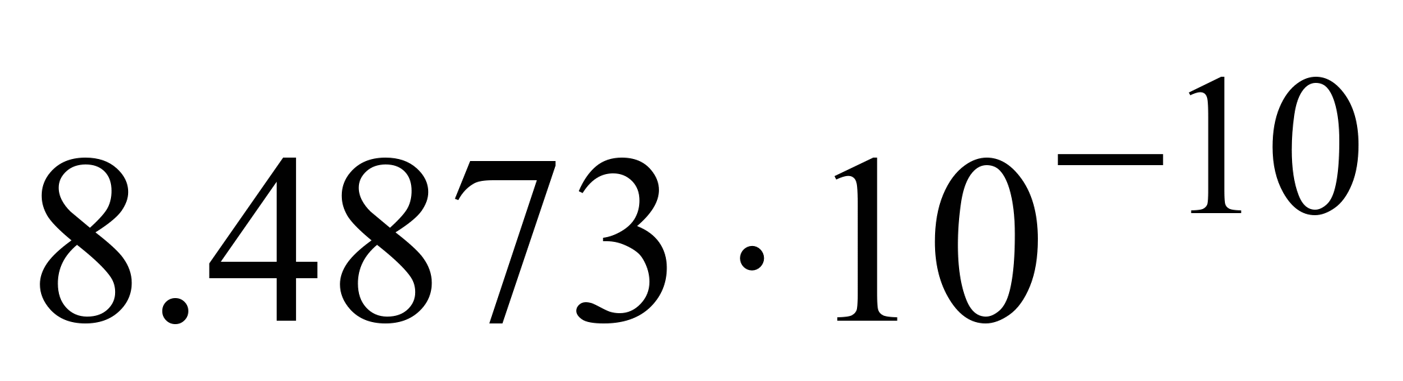
the average learning error of the NN1. MatLAB's
Fuzzy Logic Toolbox includes 11 built-in membership functions that
use the following basic functions: piecewise linear one; Gaussian
distribution; sigmoid curve; quadratic and cubic curves. The values
of the learning errors of NN1 for different membership functions are
presented in Table 6. It can be seen from the table that the
Gaussian membership function gives the smallest value of the NN1
error.
Table
6
Average
error of NN1 according to different membership
functions
|
Membership
function
|
Designation
|
Average
NFN error, 10-10
sec
|
|
triangular
|
trimf
|
8.75
|
|
trapezoidal
|
trapmf
|
10.23
|
|
bell-shaped
|
gbellmf
|
9.16
|
|
symmetric Gaussian
|
gaussmf
|
8.49
|
|
two-sided Gaussian
|
gauss2mf
|
10.03
|
|
the product of two sigmoid membership functions
|
pimf
|
13.86
|
|
Curvilinear trapezoid membership function
|
psigmf
|
10.32
|
|
the difference between two sigmoid membership functions
|
dsigmf
|
10.63
|
The
following methods of training optimization are implemented in ANFIS:
backpropagation (method based on the ideas of the quickest descent
method); hybrid (hybrid method that combines the backpropagation
method with the least-squares method). When using the
backpropagation method, the NN1 learning error is
 sec
and the hybrid method –
sec
and the hybrid method –
 sec.
That is, the error of learning the NN1 in the case of using the
hybrid method is about 13 % less than in the case of the
backpropagation method.
sec.
That is, the error of learning the NN1 in the case of using the
hybrid method is about 13 % less than in the case of the
backpropagation method.
Evaluation
of the work of the NN1. The
NN1 simulation was performed with the following parameters: packet
length – 3 850 bytes; traffic intensity – 10 packet/sec; number
of transitions – 3. The packet time on the route (from Fedorivka
junction to Dnipro junction) received in the ORNET Modeler system on
the Fast Ethernet simulation model in the ITS of Prydniprovska
Railway under the OSPFE protocol is 0.0010285 sec. (Fig. 7), and
based on NN1 –
0.000924
sec. (Fig. 8). That is, the use of NN1 allows approximately 10 %
faster determination of the route in the ITS network of
Prydniprovska Railway (for the fragment under consideration) as
compared to the OSPF protocol on the simulation model.
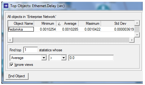
Fig. 7. Packet time on the
route (from Fedorivka to Dnipro) obtained on the simulation model
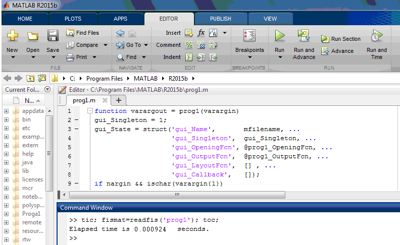
Fig. 8. Packet time on the
route (from Fedorivka to Dnipro) obtained on the NN1
Originality
and practical value
The
simulation model of Fast Ethernet network based on the OSPF scenario
and the neural fuzzy networks (NN1, NN2) can be the basis for the
integrated routing system in the ITS network of Prydnprovska
Railway,
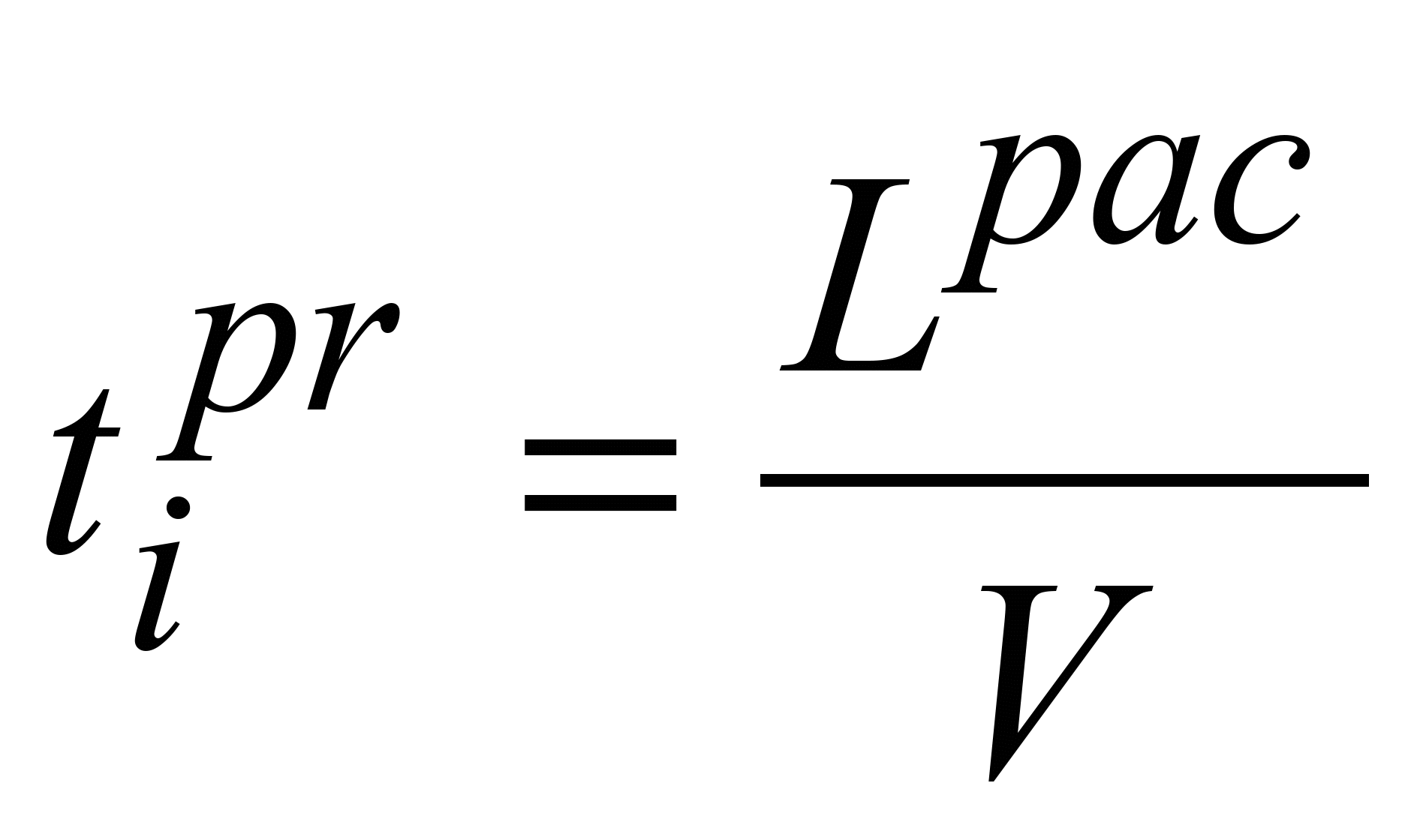
the general structure of which is shown in Fig. 9 (Lpac
–
is the packet
length;
 –
is the traffic
intensity; К
– is the number
of intermediate routers that make up the path of the packet; Tpac
–
the
packet residence time in the routers according to its path in the
network; Z_A
– total
queue delay in the routers on the path А;
Z_B
– total
queue delay in the routers on the path В).
–
is the traffic
intensity; К
– is the number
of intermediate routers that make up the path of the packet; Tpac
–
the
packet residence time in the routers according to its path in the
network; Z_A
– total
queue delay in the routers on the path А;
Z_B
– total
queue delay in the routers on the path В).
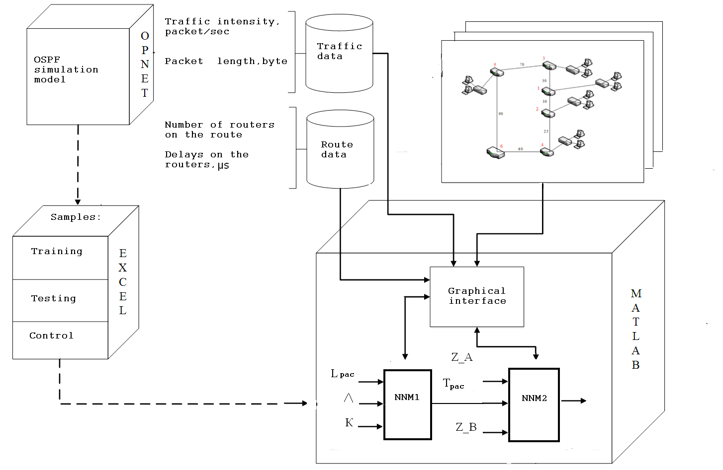
Fig. 9. General structure
of the integrated routing system in the ITS network of railway
transport:
 preparatory stage;
real time work
preparatory stage;
real time work
The
operation of the integrated routing system is demonstrated for those
fragments of the Fast Ethernet network in the ITS of Prydniprovska
Railway,
where it is possible to choose the route with the same number of
intermediate routers on different paths
(Table 7: path A
–
to the right).
Table
7
Consideration
of the ITS fragments of Prydniprovska Railway
|
|
NN1
|
NN2
|
Fragment
structure
|
Designations
|
|
Nyzhnodniprovsk–Vuzol
– Dnipro fragment
|
|
Input
parameters
|
500 bytes
|
80 μs
|
|
V1 – Ihren;
V2 – Ilarionove;
V3 – Nyzhnodniprovsk-Vuzol;
V4 –
Synelnykove –2; V5
– Nyzhnodniprovsk;
V6 –
Dnipro
|
|
10
packet/sec
|
4
μs
|
|
2
|
13
μs
|
|
Result
|
80
μs
|
1
(path
А)
|
|
Horiainove fragment
|
|
Input
parameters
|
1000
bytes
|
320
μs
|
|
V1 –
Kamianske–Pas;
V2 –
Bahlii;
V3 –
Verkhnodniprovsk;
V4 –
Sukhachivka;
V5 –
Diivka;
V6 –
Horiainove;
V7 –
Verkhivtseve;
V8 –
Vilnohirsk;
V9 –
Piatykhatky;
V10 –
Dnipro
|
|
10
packet/sec
|
29
μs
|
|
4
|
20
μs
|
|
Result
|
320
μs
|
2
(path
В)
|
|
Kryvyi Rih
fragment
|
|
Input
parameters
|
1500
bytes
|
240
μs
|
|
V1 –
Vechirnii Kut;
V2 –
Saksahan;
V3 –
Piatykhatky;
V4 –
Mudrona;
V5 –
Kryvyi Rih;
V6
– Dnipro
|
|
10
packet/sec
|
30
μs
|
|
2
|
50
μs
|
|
Result
|
240
μs
|
1
(path
А)
|
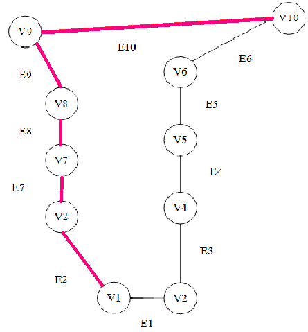
Nyzhnodniprovsk–Vuzol
– Dnipro fragment.
A packet of 500 bytes, with a traffic intensity of 10 packets/sec
and 2 transitions is transmitted from the node V1
(Ihren) to the node V6
(Dnipro). The packet residence time on the routers is predicted by
NN1
and is 80 μs. For example, depending on the values of the time
received, the total queue delay in the routers on the path А
(4
μs) and the total queue delays in the routers on the path B
(13 μs) the optimal route is chosen based on NN2: path A.
The graph showing the fragment "Nyzhnodniprovsk-Vuzol
– Dnipro" shows this route in red: V1→V2→V4→V6.
Horiainove
fragment.
A packet of 1000 bytes, with an intensity of 10 packets/sec and 4
transitions, is transmitted from the node V1
(Kamianske–Pas)
to the node V10
(Dnipro). The packet residence time in the routers is predicted by
NN1, it is 320 μs. Depending on the values of the time received,
the total queue delay in the routers on the path А
(29
μs) and the total queue delay in the routers on the path route В
(20
μs) the optimal route is chosen based on NN2: path В.
The graph showing the fragment "Horiainove"
shows this route in red:
V1→V2→V7→V8→V9→V10.
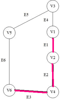
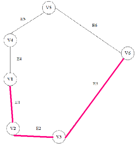
Kryvyi
Rih fragment.
A packet of 1500 byte, with an intensity of 10 packets/sec and 2
transitions, is transmitted from the node V1
(Vechirnii
Kut)
to the node V6
(Dnipro). The packet residence time in the routers is predicted by
NN1, it is 240 μs. For example, depending on the values of the time
received, the total queue delay in the routers on the path А
(30
μs) and the total queue delay in the routers on the path B
(50 μs) the optimal route is chosen based on NN2: path A.
The graph showing the fragment "Nyzhnodniprovsk-Vuzol
– Dnipro" shows this route in red: V1→V2→V3→V6.
Conclusions
According
to the structure of the ITS network of Prydniprovska Railway, a
corresponding Fast Ethernet simulation model (according to the RIP
and OSPF scenarios) was created in the ORNET Modeler system, which
defines the following characteristics: average server load; the
average time of packet processing by router; average waiting time
for packets in the queue; the average number of lost packets. It is
determined that the worst results are obtained by the simulation
model according to the RIP scenario: server load increases rapidly
(on average, about by 3 times per minute); packet processing time
by router takes much longer (approximately by 0.5 times per
minute); the waiting time for packets in the queue is always
greater (about by 1.6 times per minute); packet losses increase
rapidly (on average by 3.5 times per minute); the network
convergence time is almost twice as large.
To
determine the packet residence time in the routers on the route by
its transmission in the ITS network of the Prydniprovska Railway
NN1 was created, to the input of which the following parameters are
supplied: packet length (3 term sets); traffic intensity (5 term
sets); the number of intermediate routers in the route (4 term
sets). The following samples were formed on the simulation model of
the ITS network of Prydniprovska Railway: training (60 examples),
test (24 examples) and control (12 examples). It has been estimated
that for the considered fragment of the railway ITS network, in
particular Prydniprovska Railway, the packet time on the route
based on NN1 decreased by about 10% compared to the OSPF protocol
on the simulation model.
On
the created NN1 the study of the average error of its training for
different membership functions was performed: triangular;
trapezoidal; bell-shaped;
symmetric and two-sided Gaussian and by different methods of
training optimization (hybrid and backpropagation). It is
determined that the lowest value of the average error
 sec NN1 gives in the case of using the symmetric Gaussian
membership function according to the hybrid optimization method.
sec NN1 gives in the case of using the symmetric Gaussian
membership function according to the hybrid optimization method.
To
determine the packet path in the ITS network of Prydniprovska
Railway (provided the same number of routers that make up the
path), the NN2 was created, to the input of which the following
parameters are supplied: the packet time in the routers on the path
of its transition, the total queue delay in the routers on the path
А;
the total queue delay in the routers on the path В.
Using the simulation model of the ITS network of railway transport
the following samples were formed: training (75 examples), test (20
examples) and control (10 examples).
Based
on the created Fast Ethernet simulation model and neural fuzzy
networks (NN1 and NN2), an integrated routing system was proposed
in the ITS of Prydniprovska Railway was proposed. Using this
system, for example, the optimal route for the fragment
"Nyzhnodniprovsk-Vuzol
– Dnipro" is
determined: path A (Ihren, Ilarionove, Synelnykove–2, Dnipro)".
Асланов,
А. М. Исследование интеллектуального
подхода в маршрутизации компьютерных
сетей / А. М. Асланов, М. С. Солодовник
// Электротехнические и компьютерные
системы. – 2014. – № 16
(92).
– С. 93–100.
Коваленко,
Т. А. Разработка и исследование
интегрированной системы маршрутизации
в компьютерных сетях
:
автореф. дис. ... канд. техн. наук
:
05.13.15 / Коваленко
Татьяна Анатольевна
; СГУ.
– Самара, 2012. – 16
с.
Колесніков,
К. В. Аналіз результатів дослідження
реалізації задачі маршрутизації на
основі нейронних мереж та генетичних
алгоритмів / К. В. Колесніков, А. Р.
Карапетян, В. Ю. Баган // Вісн. Черкас.
держ. технол. ун-ту. Серія: Технічні
науки : зб. наук. пр. – Черкаси, 2016. – №
1. – C. 28–34.
Кутыркин,
А. В. Использование нейронной сети
Хопфилда для решения оптимизационных
задач маршрутизации : метод. указания
/ А. В. Кутыркин, А. В. Семин. – Москва :
Изд-во Моск. гос. ун-та путей сообщения,
2007. – 15 с.
Никитченко,
В. В. Утилиты моделирующей системы
Opnet Modeler / В. В. Никитченко. – Одесса :
Одес.
нац. акад. связи им. А. С. Попова, 2010. –
128 с.
Павленко,
М. А. Анализ возможностей искусственных
нейронных сетей для решения задач
однопутевой маршрутизации в ТКС
[Electronic
resource]
/ М. А. Павленко // Проблеми телекомунікацій.
– 2011. – № 2 (4). – Available
at:
http://pt.journal.kh.ua/index/0-139 – Title
from
the
screen.
– Accessed
: 26.09.2019.
Пахомова,
В. М. Дослідження інформаційно-телекомунікаційної
системи залізничного транспорту з
використанням штучного інтелекту :
монографія / В. М. Пахомова. – Дніпро :
Стандарт-Сервіс, 2018. – 220 с.
Реалізація
задачі вибору оптимального авіамаршруту
нейронною мережею Хопфілда / А. М.
Бриндас, П. І. Рожак, Н. О. Семенишин, Р.
Р. Курка // Наук. вісн. НЛТУ України : зб.
наук.-техн. пр. – Львів, 2016. –
Вип. 26.1. –
С. 357–363.
Тарасян,
В. С. Пакет Fuzzy Logic
Toolbox for
MatLAB : учебное пособие /
В. С. Тарасян. – Екатеринбург :
Изд-во УрГУПС, 2013. – 112 с.
Штовба,
С. Д. Проектирование нечетких систем
средствами MatLAB / С. Д.
Штовба. – Москва : Горячая
линия – Телеком, 2007. – 288 c.
Hopfield,
J. J. Neural networks and physical systems with emergent collective
computational abilities /
J.
J. Hopfield // Proceedings of National Academy of Sciences. –
1982. – Vol.
79. – Іss.
8. – P.
2554–2558.
doi: 10.1073/pnas.79.8.2554
Iqbal,
A. Performance Evaluation of Real Time Applications for RIP, OSPF
and EIGRP for flapping links using OPNET Modeler [Electronic
resource] // A. Iqbal, S. L. Ali Khan / International Journal of
Computer Networks and Communications Security. – 2015. – Vol.
3, No. 1. – Available at:
http://www.ijcncs.org/published/volume3/issue1/p4_3-1.pdf – Title
from the screen. – Accessed : 26.09.2019
Kumar,
M. V. Soft Computing: Fuzzy Logic Approach in Wireless Sensors
Networks / M.
V.
Kumar, Dr. T. Lalitha
// Circuits and Systems. –
2016. – Vol. 07. – Iss. 08. – P.
1242–1249.doi:
10.4236/cs.2016.78108
New
algorithm for packet routing in mobile ad-hoc networks / N. S.
Kojić, M. B. Zajeganović-Ivančić, I. S. Reljin, B. D.
Reljin // Journal of Automatic Control. – 2010. – Vol. 20.
– Іss.
1. – P. 9–16.
doi: 10.2298/JAC1001009K
Pakhomova,
V.
M.
Intelligent
routing in the network of information and telecommunication system
of railway transport
/ V. M. Pakhomova, T.
I. Skaballanovich, V. S. Bondareva //
Наука та прогрес транспорту.
– 2019.
– № 2
(80).
– P.
77–90.
10.15802/stp2019/166092
Pakhomova,
V. M. Optimal route definition in the network based on the
multilayer neural model / V. M. Pakhomova, I. D. Tsykalo // Наука
та
прогрес
транспорту.
– 2018. – № 6 (78). – P. 126–142. doi:
10.15802/stp2018/154443
Sasikala,
K. A neuro fuzzy based conditional shortest path routing protocol
for wireless mesh network / K. Sasikala, V.
Rajamani
// International Journal of Enhanced Research in Management &
Computer Applications. –2013. – Vol. 2. – Iss. 5. – P.
1–10.
Schuler,
W. H. A novel hybrid training method for hopfield neural networks
applied to routing in communications networks / W. H. Schuler, C.
J. A. Bastos-Filho, A. L. I. Oliveira // International Journal of
Hybrid Intelligent Systems. – 2009. – Vol. 6. – Іss. 1. –
P. 27–39. doi: 10.3233/his-2009-0074
Towards
QoS-aware routing for DASH utilizing MPTCP over SDN / K. Herguner,
R. S. Kalan, C. Cetinkaya, M. Sayit // IEEE Conference on Network
Function Virtualization and Software Defined Networks (NFV-SDN)
(6–8 Nov. 2017). – Berlin, Germany, 2017. – P. 1–6. doi:
10.1109/nfv-sdn.2017.8169844
Zhukovyts’kyy,
I. Research of Token Ring network options in automation system of
marshalling yard / I. Zhukovyts’kyy, V. Pakhomova // Transport
Problems. – 2018. – Vol. 13. – Iss. 2. – P. 149–158.
В. М. ПАХОМОВА1*,
Є. С. МАНДИБУРА2*
1*Каф.
«Електронні обчислювальні машини»,
Дніпровський національний університет
залізничного транспорту імені академіка
В. Лазаряна, вул. Лазаряна, 2, Дніпро,
Україна, 49010, тел. +38 (056) 373 15 89, ел. пошта
viknikpakh@gmail.com, ORCID 0000-0002-0022-099X
2*Каф.
«Електронні обчислювальні машини»,
Дніпровський національний університет
залізничного транспорту імені академіка
В. Лазаряна, вул. Лазаряна, 2, Дніпро,
Україна, 49010, тел. +38 (056) 373 15 89, ел. пошта
mandybura1994@gmail.com,
ORCID 0000-0002-7134-9416
ВИЗНАЧЕННЯ ОПТИМАЛЬНОГО
МАРШРУТУ
В ІНФОРМАЦІЙНІЙ МЕРЕЖІ
ЗАЛІЗНИЧНОГО
ТРАНСПОРТУ З ВИКОРИСТАННЯМ
НЕЙРОНЕЧІТКИХ МОДЕЛЕЙ
Мета. Сучасні
алгоритми вибору найкоротшого маршруту,
наприклад, алгоритми Беллмана–Форда
й Дейкстри, які в даний час широко
використовують у протоколах маршрутизації
(RIP, OSPF), не завжди призводять до ефективного
результату. Тому виникає необхідність
дослідження можливості організації
маршрутизації в мережі
інформаційно-телекомунікаційної
системи (ІТС) залізничного транспорту
за допомогою методів штучного інтелекту.
Методика. На
основі створеної в моделювальній
системі OPNET імітаційної
моделі розглянуто фрагмент мережі ІТС
залізничного транспорту й сформовано
наступні вибірки: навчальну;
тестувальну; контрольну. Для моделювання
в системі MatLAB
нейронечіткої мережі (гібридної системи)
на вхід подають наступні
параметри: довжина пакета (3 терм-множини);
інтенсивність трафіка (5 терм-множин);
кількість
проміжних маршрутизаторів, що складають
маршрут (4 терм-множини).
За результуючу характеристику взято
час перебування пакета в маршрутизаторах
за маршрутом його проходження в мережі
ІТС (4 терм-множини).
На основі визначеного часу перебування
пакета в маршрутизаторах і
затримок у черзі на маршрутизаторах,
що складають різні шляхи (з однаковою
кількістю маршрутизаторів) визначено
оптимальний маршрут. Результати.
Для розглянутого фрагмента ІТС
залізничного транспорту
здійснено прогноз часу
перебування пакета в маршрутизаторах
за маршрутом його проходження на основі
нейронечіткої мережі, що створена в
системі MatLAB. Проведено дослідження
середньої похибки навчання нейронечіткої
мережі за різних функцій належності й
за різними методами оптимізації
навчання. Виявлено, що найменше значення
середньої похибки навчання
надає нейронечітка
мережа конфігурації 3–12–60–60–1
в разі використання симетричної
Гаусівської функції належності за
гібридним методом оптимізації. Наукова
новизна. За
сценаріями RIP та OSPF на створеній в
моделювальній системі OPNET імітаційній
моделі отримані наступні характеристики:
середнє навантаження сервера; середній
час обробки пакетів маршрутизатором;
середній час очікування пакетів у
черзі; середня кількість втрачених
пакетів; час конвергенції мережі.
Визначено, що
найкращі результати надає імітаційна
модель мережі за сценарієм OSPF.
Запропонована інтегрована
система маршрутизації в
мережі ІТС залізничного транспорту,
в основу якої покладено створені
нейронечіткі мережі, визначає
оптимальний маршрут у мережі швидше
порівняно з наявним протоколом
маршрутизації OSPF.
Практична значимість.
Інтегрована система маршрутизації в
ІТС залізничного транспорту
дозволить у реальному часі
визначити оптимальний маршрут у мережі
за однаковою кількістю маршрутизаторів,
що складають шлях проходження пакета.
Ключові
слова:
маршрутизація; протокол OSPF; імітаційна
модель; гібридна система; терм; функція
належності; вибірка; похибка
В. Н. ПАХОМОВА1*,
Е. С. МАНДЫБУРА2*
1*Каф.
«Электронные вычислительные машины»,
Днипровский национальный университет
железнодорожного транспорта имени
академика В. Лазаряна, ул. Лазаряна, 2,
Днипро, Украина,
49010, тел. +38 (056) 373 15 89,эл. почта
viknikpakh@gmail.com,
ORCID 0000-0002-0022-099X
2*Каф.
«Электронные вычислительные машины»,
Днипровский национальный университет
железнодорожного транспорта имени
академика В. Лазаряна, ул. Лазаряна, 2,
Днипро, Украина, 49010, тел.
+38 (056) 373 15 89, эл. почта
mandybura1994@gmail.com,
ORCID 0000-0002-7134-9416
ОПРЕДЕЛЕНИЕ
ОПТИМАЛЬНОГО МАРШРУТА
В
ИНФОРМАЦИОННОЙ
СЕТИ
ЖЕЛЕЗНОДОРОЖНОГО ТРАНСПОРТА
С
ИСПОЛЬЗОВАНИЕМ НЕЙРОНЕЧЕТКИХ МОДЕЛЕЙ
Цель. Современные алгоритмы выбора
кратчайшего маршрута, например, алгоритмы
Беллмана–Форда и Дейкстры,
которые в настоящее время широко
используют в протоколах маршрутизации
(RIP, OSPF), не всегда приводят к эффективному
результату. Поэтому возникает
необходимость исследования возможности
организации маршрутизации в сети
информационно-телекоммуникационной
системы (ИТС)
железнодорожного транспорта с помощью
методов искусственного интеллекта.
Методика. На основе созданной в
моделирующей системе OPNET имитационной
модели рассмотрен фрагмент сети ИТС
железнодорожного транспорта и
сформированы следующие выборки:
обучающая; тестирующая; контрольная.
Для моделирования в системе MatLAB
нейронечеткой сети (гибридной системы)
на вход подают следующие параметры:
длина пакета (3 терм-множества);
интенсивность трафика (5 терм-множеств);
количество промежуточных маршрутизаторов,
составляющих маршрут (4 терм-множества).
В качестве результирующей характеристики
принято время пребывания пакета в
маршрутизаторах по маршруту его
следования в сети ИТС (4 терм-множества).
На основе полученного времени пребывания
пакета в маршрутизаторах и задержек в
очереди на маршрутизаторах, составляющих
различные пути (с одинаковым количеством
маршрутизаторов) определен оптимальный
маршрут. Результаты. Для рассматриваемого
фрагмента ИТС железнодорожного
транспорта осуществлен прогноз времени
пребывания пакета в маршрутизаторах
по маршруту его следования на основе
нейронечеткой сети, созданной в системе
MatLAB. Проведено исследование средней
погрешности обучения нейронечеткой
сети при различных функциях принадлежности
и разных методов оптимизации обучения.
Обнаружено, что наименьшее значение
средней погрешности обучения предоставляет
нейронечеткая сеть конфигурации
3–12–60–60–1 при использовании симметричной
Гауссовской функции
принадлежности с гибридным методом
оптимизации. Научная новизна. По
сценариям RIP и OSPF на созданной в
моделирующей системе OPNET имитационной
модели получены следующие характеристики:
средняя нагрузка сервера; среднее время
обработки пакетов маршрутизатором;
среднее время ожидания пакетов в
очереди; среднее количество потерянных
пакетов; время конвергенции сети.
Определено, что наилучшие результаты
дает имитационная модель сети по
сценарию OSPF. Предложенная интегрированная
система маршрутизации в сети ИТС
железнодорожного транспорта, в основу
которой положены созданные нейронечеткие
модели, определяет оптимальный маршрут
в сети быстрее по сравнению с существующим
протоколом маршрутизации OSPF. Практическая
значимость. Интегрированная система
маршрутизации в ИТС железнодорожного
транспорта позволит в реальном времени
определить оптимальный маршрут в сети
с одинаковым количеством маршрутизаторов,
составляющих путь прохождения пакета.
Ключевые слова: маршрутизация;
протокол OSPF; имитационная модель;
гибридная система; терм; функция
принадлежности; выборка; погрешность
REFERENCES
Aslanov,
A. M., & Solodovnik,
M. S. (2014). Issledovanie intellektualnogo podkhoda v
marshrutizatsii kompyuternykh setey. Elektrotekhnicheskie
i kompyuternye sistemy, 16(92),
93-100. (in Russian)
Kovalenko,
T. A. (2012). Razrabotka
i issledovanie integrirovannoy sistemy marshrutizatsii v
kompyuter-nykh setyakh.
(Avtoreferat
dysertatsii kandydata tekhnichnykh
nauk). SGU,
Samara. (in Russian)
Kolesnikov,
K. V., Karapetian, A. R., &
Bahan, V. Y. (2016). Analiz rezultativ doslidzhennia realizatsii
zadachi marshrutyzatsii na osnovi neironnykh merezh ta henetychnykh
alhorytmiv. Visnyk Cherkaskogo
derzhavnogo tehnologichnogo universitetu. Seria: Tehnichni nauky,
1, 28-34. (in
Ukrainian)
Kutyrkin,
A. V., & Semin, A. V. (2007). Ispolzovanie
neyronnoy seti Khopfilda dlya resheniya optimizatsionnykh zadach
marshrutizatsii: Metodicheskie ukazaniya.
Moscow:
Izdatelstvo Moskovskogo gosudarstvennogo universiteta putey
soobshcheniya. (in Russian)
Nikitchenko,
V. V. (2010). Utility modeliruyushchey
sistemy Opnet Modeler. Odessa:
Odesskaya nat-sionalnaya
akademiya svyazi im. A. S. Popova. (in Russian)
Pavlenko,
M. A. (2011). Analysis
opportunities of artificial neural networks for solving single-path
routing in telecommunication network. Problemy
telekomunikatsii, 2(4). Retrieved
from
http://pt.journal.kh.ua/index/0-139
(in Russian)
Pakhomova,
V. M. (2018). Doslidzhennia
informatsiino-telekomunikatsiinoi systemy zaliznychnoho transportu
z vykorystanniam shtuchnoho intelektu: monohrafiia.
Dnipro: Standart-Servis. (in Ukrainian)
Bryndas,
A. M., Rozhak, P. I., Semenishin, N. O., & Kurka, R. R. (2016).
Implementing of the Problem of Choosing the Optimal Flight Rout by
a Hopfield Neural Network. The
Scientific Bulletin of UNFU, 26.1, 357-363.
(in Ukrainian)
Tarasyan,
V. S. Paket Fuzzy Logic Toolbox for MatLAB: uchebnoe posobie.
(2013)
Yekaterinburg: Izdatelstvo:
UrGUPS.
(in Russian)
Shtovba,
S. D. (2007). Proektirovanie
nechetkikh sistem sredstvami MatLAB.
Moscow:
Goryachaya liniya–Telekom. (in Russian)
Hopfield,
J. J. (1982). Neural networks and physical systems with emergent
collective computational abilities. Proceedings
of National Academy of Sciences, 79(8), 2554-2558. doi:
10.1073/pnas.79.8.2554
(in English)
Iqbal,
A., & Ali Khan, S. L. (2015). Performance Evaluation of Real
Time Applications for RIP, OSPF and EIGRP for flapping links using
OPNET Modeler. International
Journal of Computer Networks and Communications Security, 3(1).
Retrieved from:
http://www.ijcncs.org/published/volume3/issue1/p4_3-1.pdf (in
English)
Kumar,
M. V., & Lalitha,
Dr.
T. (2016). Soft
Computing: Fuzzy Logic Approach in Wireless Sensors Networks.
Circuits
and Systems,
07(08),
1242–1249.
doi: 10.4236/cs.2016.78108
(in English)
Kojić,
N. S., Zajeganović-Ivančić, M. B., Reljin, I. S., & Reljin
B. D. (2010). New algorithm for packet routing in mobile ad-hoc
networks. Journal of Automatic
Control, 20(1), 9-16. doi:
10.2298/jac1001009k
(in English)
Pakhomova,
V. M., Skaballanovich, T. I., &
Bondareva, V. S. (2019). Intelligent
routing in the network of information and telecommunication system
of railway transport. Science and
Transport Progress, 2(80), 77-90.
doi:
10.15802/stp2019/166092
(in English)
Pakhomova,
V. M. & Tsykalo, I. D. (2018). Optimal route definition in the
network based on the multilayer neural model. Science
and Transport Progress, 6(78),
126-142. doi: 10.15802/stp2018/154443
(in English)
Sasikala,
K. & Rajamani,
V. (2013). A neuro
fuzzy based conditional shortest path routing protocol for wireless
mesh network. International
Journal of Enhanced Research in Management & Computer
Applications, 2(5),
1-10. (in English)
Schuler,
W. H., Bastos-Filho, C. J. A., & Oliveira, A. L. I. (2009). A
novel hybrid training method for hopfield neural networks applied
to routing in communications networks. International
Journal of Hybrid Intelligent Systems, 6(1),
27-39. doi: 10.3233/his-2009-0074
(in
English)
Herguner,
K., Kalan, R. S., Cetinkaya, C., & Sayit, M. (2017). Towards
QoS-aware routing for DASH utilizing MPTCP over SDN. 2017
IEEE Conference on Network Function Virtualization and Software
Defined Networks (NFV-SDN).
doi: https://doi.org/10.1109/nfv-sdn.2017.816984
(in
English)
Zhukovyts’kyy,
I. & Pakhomova, V. (2018). Research of Token Ring network
options in automation system of marshalling yard. Transport
Problems, 13(2),
145-154. (in English)
Received:
May 15, 2019
Accepted:
September 12,
2019
© В. М. Пахомова, Є.
С. Мандибура 2019