ISSN
2307–3489 (Print), ІSSN
2307–6666
(Online)
Наука
та прогрес транспорту. Вісник
Дніпропетровського
національного університету залізничного
транспорту, 2019,
№ 4 (82)
рухомий
склад і тяга поїздів
рухомий
склад і тяга поїздів
UDC
629.463.62.027.4:625.143.3.033.373
O.
V. Shatunov1*,
A.
O. shvets2*,
O. A. KIRILCHUK3*,
A.
O. shvets4*
1*Dep.
«Cars and Car
Facilities»,
Dnipro National University of Railway
Transport named after
Academician V. Lazaryan, La-zaryan St., 2, Dnipro,
Ukraine, 49010,
tel. +38 (067) 953 60 14, e-mail shatunov220648@gmail.com,
ORCID
0000-0002-1115-0093
2*Dep.
«Theoretical and
Structural Mechanics»,
Dnipro National University of Railway
Transport named after
Academician V. Lazaryan, Lazaryan St., 2, Dnipro,
Ukraine, 49010,
tel. +38 (050) 214 14 19, e-mail angela.shvets69@gmail.com,
ORCID
0000-0002-8469-3902
3*Dep.
«Car and Car Facilities», Dnipro National University of Railway
Transport named after Academician V. Lazaryan,
Lazaryan St., 2,
Dnipro, Ukraine, 49010, tel./fax +38 (056) 776 82 27,
e-mail
o.a.kirilchuk@gmail.com,
ORCID 0000-0002-0565-1692
4*Dep.
«Car and Car Facilities», Dnipro National University of Railway
Transport named after Academician V. Lazaryan,
La-zaryan St., 2,
Dnipro, Ukraine, 49010, tel./fax +38 (095) 235 19 67,
e-mail
angela_Shvets@ua.fm, ORCID 0000-0002-0717-2521
RESEARCH
OF WHEEL-RAIL WEAR due
to
non-SYMMETRICAL
LOADING
OF a FLAT
car
Purpose.
The paper is aimed at determining the
influence of non-symmetrical loading of a flat car on the magnitude
of the wear factor of a wheel-rail pair when changing the operation
parameters that occur in operation.
Methodology.
The dynamic loading of the flat car, model 13-401 with typical
three-piece bogies is studied using a model of spatial oscillations
of a five-car coupling with the help of mathematical and computer
simulation. Theoretical calculations are performed for the most
dangerous sections of the railway track-small and medium radius
curves in the range of permissible speeds. Findings.
The indicators of wear of the rolling stock
wheels and the rails are analysed on the example of flat cars in the
presence of a longitudinal and transverse displacement of the load
mass centre relative to the car symmetry centre. To obtain
information on the effect of permissible deviations of the
arrangement of cargo in the car on the magnitude of the dynamic
loading of the wheel-rail contact, the authors performed theoretical
studies of the spatial variations of the rail carriage and its
interaction with the track. Originality.
To determine the wear of the wheel-rail pair, the effect of
displacement in two directions from the central axis of symmetry of
the load gravity centre was studied, taking into account the value of
the travel speed along the curved sections of the small and medium
radius using a mathematical model of coupling of five freight cars.
Practical value.
As a result of the theoretical studies carried out, the authors
assessed such factors as wear factor,
directional force, and hunting of the wheel set of freight rolling
stock in the event of load gravity centre displacement when moving
along curved sections of the railway track. To establish the possible
cause of intensive wear of the wheels and rails, the following
parameters were analysed: lozenging of front bogie side frames;
hunting of the left side frame of the front bogie; mutual
longitudinal movement of the side frame and axle box of the front
wheel set; mutual hunting of the left side frame of the bogie
relative to the front wheel set.
Keywords:
load; flat
car; lozenging
of bogie side
frames; load
gravity centre
displacement; angle
of wheel set
hunting; travel speed;
wear factor
Introduction
The
intensity of
the wheel-rail
wear is
so far
one of
the most
serious problems
of rail
transport.
The analysis of publications and studies
related to this issue has shown that increased wear of rails and
rolling stock can be caused by several reasons associated with both
the state of the carriage chassis and the state of the rail track in
curved sections [5, 8, 9, 16].
Wear of wheels and rails depends
on physical and mechanical processes occurring in the area of their
contact. The nature of these processes and their intensity depend to
a large extent on external influences on the surface of the contact
point, in particular, on the interaction forces of the contacting
bodies and their relative displacements. Therefore, one of the
possible ways to solve the problem of reducing the intensity of wear
of the wheel flanges and rail head side surfaces is to establish
conditions for reducing external impacts on the contacting bodies,
or reducing the dynamic loading of the contact point. Of particular
importance are the reciprocal movements of the contacting bodies, as
the wear is associated with the work of friction (pseudo-slipping
forces) in the contact area. Therefore, the solution to this problem
is to minimize the forces of interaction and mutual displacement of
the wheel-rail pair in the points of contact.
Determination of the wear index
is connected with the task of studying spatial oscillations and the
interaction of rail carriage and track. For solving this problem the
Dnpro National University of Railway Transport named after
Academician V. Lazaryan developed the mathematical models that make
it possible to determine the necessary values of forces and
displacements, and to obtain the wear indicator as the resultant
value [2-4, 12, 15]. With these models, it is possible to obtain
solutions for various types of wheel-rail contact, to take into
account the rigidity of the structural elements and the various
deviations from the initial configuration of the system, such as the
misalignment of the wheel set axles in the bogie, the difference in
the wheel radii of one wheel set, of different wheel sets in a bogie
and different bogies, rail gradient and wheel profile of various
types, change in the cross gap of the wheel set and rail track, the
change of longitudinal and cross clearance between the axle-boxes
and side frames, the displacement of the body mass center relative
to the car symmetry, etc. [5, 13, 17-19, 20-22].
Purpose
The purpose of this study is to
determine the influence of non-symmetrical loading of a flat car on
the magnitude of the wear factor of a wheel-rail pair when changing
the operation parameters.
Methodology
Theoretical
studies of the dynamic loading of the wheel-rail contact during the
movement of 13-401 model flat car with typical bogies 18-100 in the
speed range
 km/h in the small and middle radius curves
were performed using the model of spatial oscillations of a five-car
coupling (Fig. 1) [2-4, 6, 10, 21].
km/h in the small and middle radius curves
were performed using the model of spatial oscillations of a five-car
coupling (Fig. 1) [2-4, 6, 10, 21].
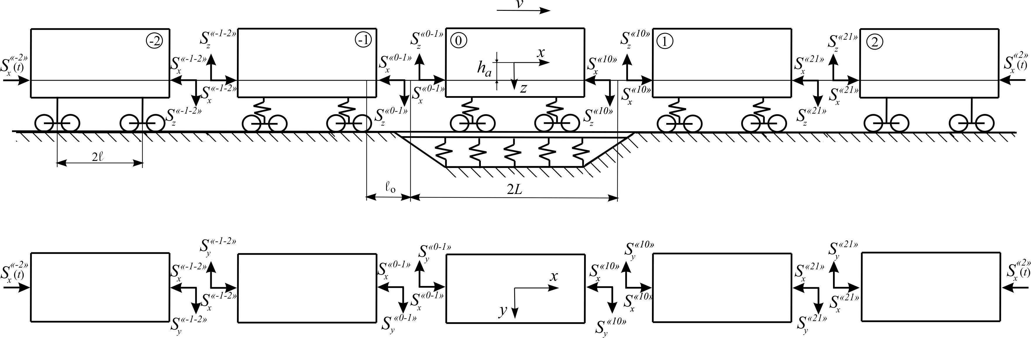
Fig. 1. Design
diagram of the five-freight-car coupling
The flat car is considered as a
mechanical system (Fig. 2), which consists of 12 solids (load, car
frame, two bolsters, four bogie side frames, four wheel sets).
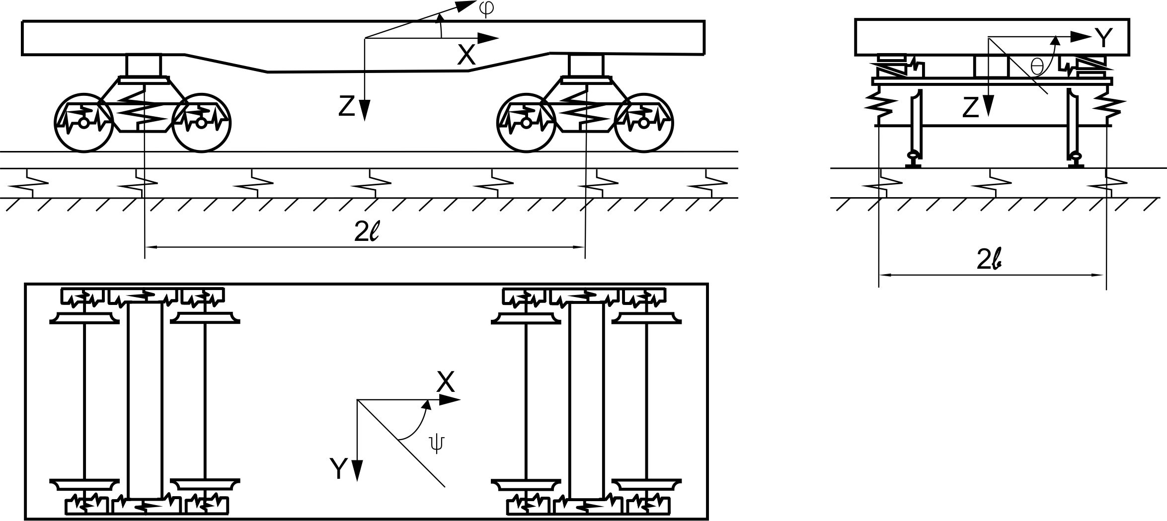
Fig. 2. Design
diagram of the 4-axle flat car
In our
research we studied the effect of the load mass center shift on the
flat car frame in the longitudinal
 and transverse directions
,
as well as in both directions
simultaneously. Preliminary theoretical studies have shown that in
the presence of a transverse or simultaneous transverse and
longitudinal displacement of the load mass center over
and transverse directions
,
as well as in both directions
simultaneously. Preliminary theoretical studies have shown that in
the presence of a transverse or simultaneous transverse and
longitudinal displacement of the load mass center over
 m there is a sharp decrease in the
derailment coefficient and a high probability of rolling stock
derailment [21].
m there is a sharp decrease in the
derailment coefficient and a high probability of rolling stock
derailment [21].
In
order to
determine the
effect of
only the
load mass
centre
displacement on
the factor
of wheel
and rail
wear, the
displacement in
the transverse
and simultaneous
transverse and
longitudinal
directions is
considered
within the
limits
 m and
m and .
The stationary movement of a
five-freight-car coupling in the right curve is studied.
Consequently, the left wheel of the first wheel set climbs the outer
rail. The carriage chassis, the wheel rolling surface and the rail
head profile are provided in a normal technical condition.
.
The stationary movement of a
five-freight-car coupling in the right curve is studied.
Consequently, the left wheel of the first wheel set climbs the outer
rail. The carriage chassis, the wheel rolling surface and the rail
head profile are provided in a normal technical condition.
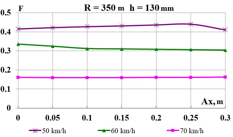
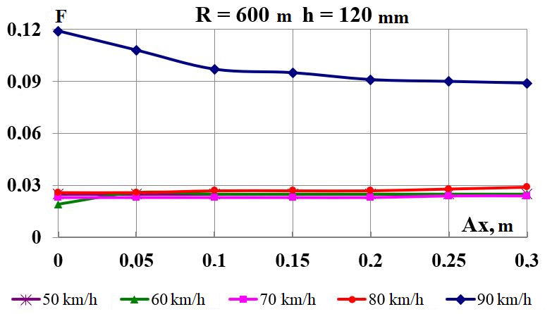
Findings
The graphs of
variance of the studied parameters during the movement in the curve
sections of the track
 and 350 m are shown in Fig. 3-8. The
displacement in the longitudinal direction (Fig. 3, 4) is considered
in the range from 0 to
and 350 m are shown in Fig. 3-8. The
displacement in the longitudinal direction (Fig. 3, 4) is considered
in the range from 0 to
 .
For a detailed analysis of the physical processes occurring during
the sliding of the wheel flange on the rail side face, it is
necessary to investigate the corresponding dependences of the
directional force and the striking angle of the wheel set [5].
.
For a detailed analysis of the physical processes occurring during
the sliding of the wheel flange on the rail side face, it is
necessary to investigate the corresponding dependences of the
directional force and the striking angle of the wheel set [5].
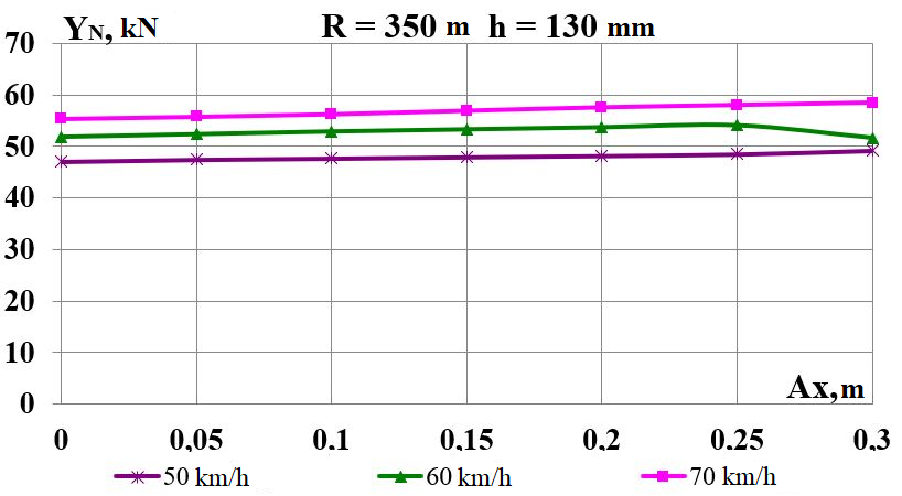
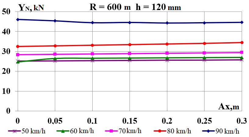
As
can be
seen from
Fig. 3 (a,
b),
increase of
the longitudinal
displacement of
the load
mass center
has almost
no effect
on the
wear factor.
This indicator
is significantly
influenced by
the travel
speed. In
curves
 m, the
wear factor
F with
an increase
in speed
from 50 to
70 km/h
decreases by
2.7 times. The
wear factor
in the
curves of
the small
radius is
greater than
the
corresponding
values in
the curves
of the
average radius
by 16.8÷6.7
times in
the speed
range
m, the
wear factor
F with
an increase
in speed
from 50 to
70 km/h
decreases by
2.7 times. The
wear factor
in the
curves of
the small
radius is
greater than
the
corresponding
values in
the curves
of the
average radius
by 16.8÷6.7
times in
the speed
range
 km/h.
This can
be explained
by the
higher levels
of the
directional
forces
km/h.
This can
be explained
by the
higher levels
of the
directional
forces
 (Fig. 3, c,
d)
and the
hunting angles
(Fig. 3, c,
d)
and the
hunting angles
 (Fig. 3, e,
f) in
the curves
m. At
a speed of 90 km/h, the index
in case of increasing the longitudinal
displacement in the curve
m from 0 up to 0.3 m is significantly
differs from the speed interval
(Fig. 3, e,
f) in
the curves
m. At
a speed of 90 km/h, the index
in case of increasing the longitudinal
displacement in the curve
m from 0 up to 0.3 m is significantly
differs from the speed interval
 km/h and exceeds the corresponding values
by an average of 29.5%. In addition, the hunting angles
in both curves have a sign «–»,
that is, the wheel sets rotate in the track plane against the
direction of the curve in accordance with the accepted rule of the
signs (Fig. 2).
km/h and exceeds the corresponding values
by an average of 29.5%. In addition, the hunting angles
in both curves have a sign «–»,
that is, the wheel sets rotate in the track plane against the
direction of the curve in accordance with the accepted rule of the
signs (Fig. 2).
а
b
c
d
e
f
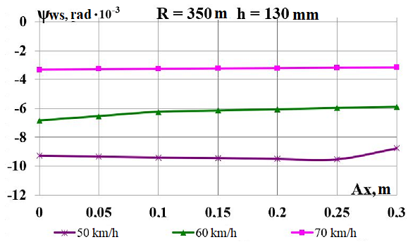
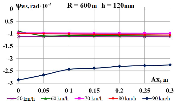
Fig.
3. Graphs of dependence on load displacement
in the longitudinal
direction:
a,
b
– wear factor; c,
d
– directional force acting from the rail side on the wheel;
e,
f
– hunting of the wheel set
The disadvantages of the
three-piece bogie of 18-100 model include the possibility of side
frames lozenging under the action of the longitudinal components of
the frictional forces on the wheel-rail contacts, which causes loss
of the bogie frame geometry and the appearance of distortions of the
wheel set axle therein. In addition, the design of the side frame
box opening and the axle box presupposes the presence of
longitudinal and transverse gaps between the box housing lug and the
box opening guides, through which the nature of their contact can
also change. This phenomenon negatively affects the dynamics of the
car and, as a result, leads to intensive wear of the wheel
flanges [1, 7, 9, 14, 23].
In addition, the mutual
longitudinal lozenging of side frames are particularly harmful when
moving along curved track sections, as they cause the turns of the
wheel sets in the track plane against the direction of the curve.
This, in turn, increases the striking angles of the wheel flanges on
the rails, resulting in their mutual wear, since this reduces the
contact area of the flange with the rail side face and, accordingly,
increases the specific pressure on it, which determines their wear.
To
determine the
probable cause
of the
intense wear
of the
wheels and
rails during
the movement
in the
curves
m, let
us consider
the following
parameters:
lozenging of side
frames of
the front
bogie; hunting
of the left side frame of the front bogie;
mutual longitudinal displacement of side
frame and axle box of the front wheel set;
mutual hunting of the bogie left side
frame relative to the front wheel set
(Fig.4).
a
b
c
d
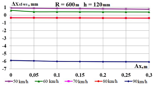
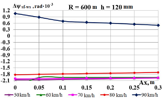
Fig.
4. Graphs of dependence on load displacement in the
longitudinal direction:
а
–
lozenging
of side frames of the front bogie;
b
–
hunting
of the left side frame of the front bogie;
c
–
mutual
longitudinal displacement of side frame and axle box of the front
wheel set;
d
–
mutual
hunting of the bogie left side frame relative to the front wheel set
a
b
c
d
e
f
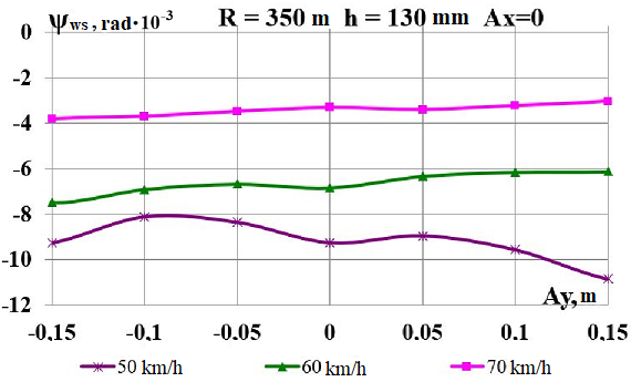
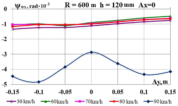
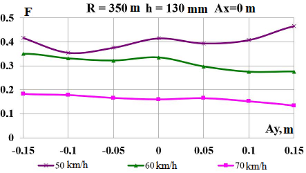
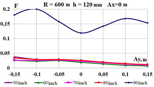
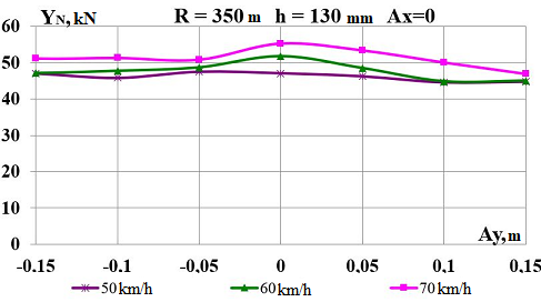
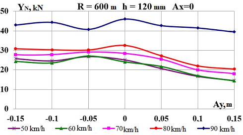
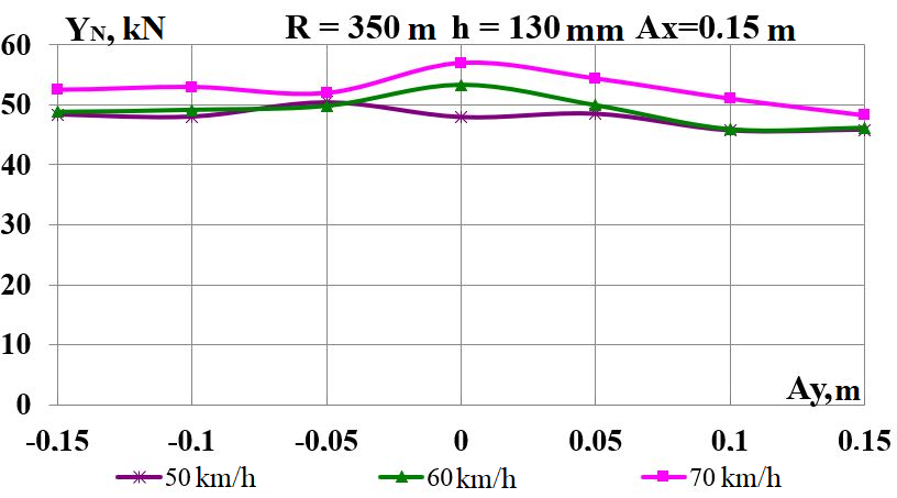
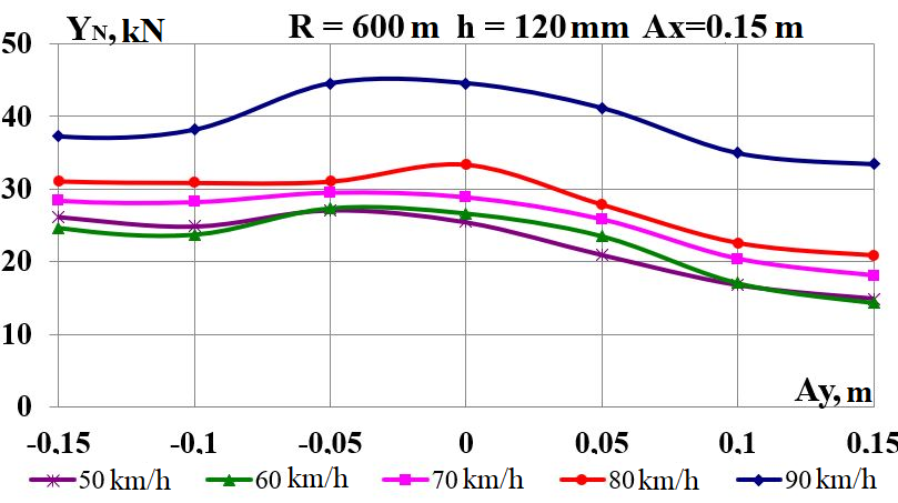
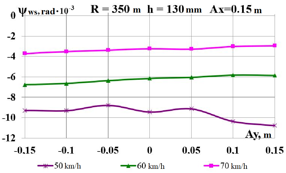
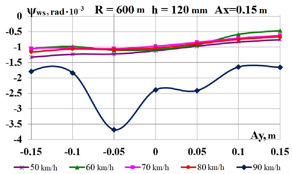
Fig.
5. Graphs of dependence on load displacement in the transverse
direction:
a,
b
– wear factor; c,
d
– directional force acting from the rail side on the wheel; e,
f
– hunting of the wheel set
Fig.
5 shows the
effect on
the studied
parameters of
the transverse
displacement of
the load
mass center
 in the
curves
m
and
m,
respectively.
With increased
the wear
factor F
(Fig. 5, a)
in the
curve
m does
not change
so linearly,
as in
case of
longitudinal
displacement,
but also
decreases in
case of
speed rise.
In the curve
m F
decreases due to the load relief of the climbing wheel. Exception
from the
general picture,
as in
the previous
case, is
the speed
of 90 km/h.
The wear factor curve F
(Fig. 5, b)
has extremes for
in the
curves
m
and
m,
respectively.
With increased
the wear
factor F
(Fig. 5, a)
in the
curve
m does
not change
so linearly,
as in
case of
longitudinal
displacement,
but also
decreases in
case of
speed rise.
In the curve
m F
decreases due to the load relief of the climbing wheel. Exception
from the
general picture,
as in
the previous
case, is
the speed
of 90 km/h.
The wear factor curve F
(Fig. 5, b)
has extremes for
 m in both directions from the axis of symmetry of the flat car
frame. In case of transverse displacement of the load mass center,
there are higher directed forces
(Fig. 5, c,
d) and hunting angles
(Fig. 5, e,
f) in the curves
m. The wheel set hunting
at the speed of 90 km/h in the curve
m is
also significantly different from the speed range
km/h and is directed in the track plane
against the direction in both curves.
m in both directions from the axis of symmetry of the flat car
frame. In case of transverse displacement of the load mass center,
there are higher directed forces
(Fig. 5, c,
d) and hunting angles
(Fig. 5, e,
f) in the curves
m. The wheel set hunting
at the speed of 90 km/h in the curve
m is
also significantly different from the speed range
km/h and is directed in the track plane
against the direction in both curves.
a
b
c
d
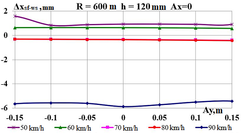
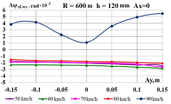
Fig.
6. Graphs of
dependence on
load
displacement in
the transverse
direction:
а
–
lozenging
of side frames of the front bogie;
b
–
hunting
of the left side frame of the front bogie;
c
–
mutual
longitudinal displacement of side frame and axle box of the front
wheel set;
d
–
mutual
hunting of the bogie left side frame relative to the front wheel set
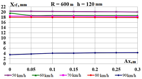
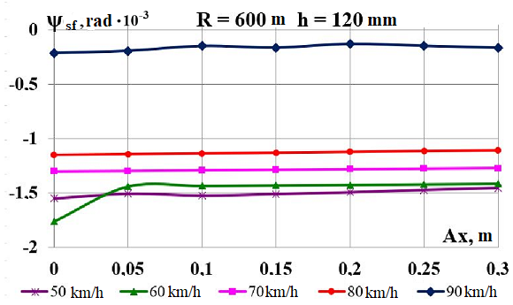
Graphic
dependencies in Fig. 6 show that the front bogie side frame hunting
 (Fig. 6, a)
at speed of 90 km/h are 7 times smaller than in the range of
km/h
and 2 times smaller than at equivalent value for longitudinal
displacement. Comparing Fig.
4, b
and Fig. 6, b,
we should note that the presence of a transverse displacement of the
load mass center on the flat car leads to significant changes in the
nature of the hunting of the left side frame of the front bogie
(Fig. 6, a)
at speed of 90 km/h are 7 times smaller than in the range of
km/h
and 2 times smaller than at equivalent value for longitudinal
displacement. Comparing Fig.
4, b
and Fig. 6, b,
we should note that the presence of a transverse displacement of the
load mass center on the flat car leads to significant changes in the
nature of the hunting of the left side frame of the front bogie
 at a speed of 90 km/h. The hunting
angles
(Fig. 6, b)
also have the «–»
sign. As for longitudinal displacement, a significant increase in
the wheel set hunting angles
occurs due to significant mutual
longitudinal displacements of the side frame and the axle box of the
front wheel set
at a speed of 90 km/h. The hunting
angles
(Fig. 6, b)
also have the «–»
sign. As for longitudinal displacement, a significant increase in
the wheel set hunting angles
occurs due to significant mutual
longitudinal displacements of the side frame and the axle box of the
front wheel set (Fig. 6, c),
as well as the hunting of the left side frame of the bogie relative
to the front wheel set through the shift of the boxes in the side
frame openings
(Fig. 6, c),
as well as the hunting of the left side frame of the bogie relative
to the front wheel set through the shift of the boxes in the side
frame openings
 (Fig. 6, d).
With the exception of the speed of 90 km/h, the values of the
indicators
and
due to the load shift in the transverse
direction decrease in case of additional loading of the non-climbing
wheel.
(Fig. 6, d).
With the exception of the speed of 90 km/h, the values of the
indicators
and
due to the load shift in the transverse
direction decrease in case of additional loading of the non-climbing
wheel.
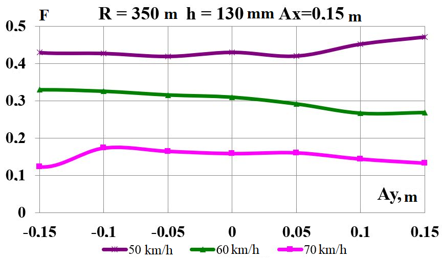
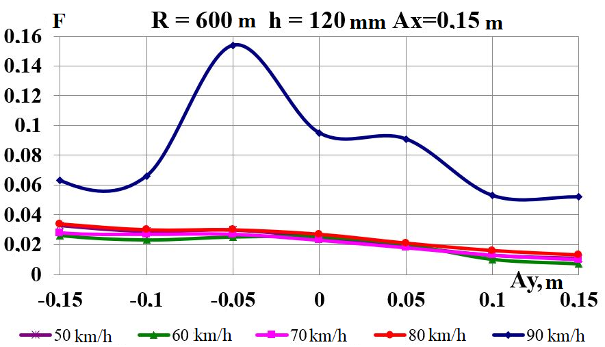
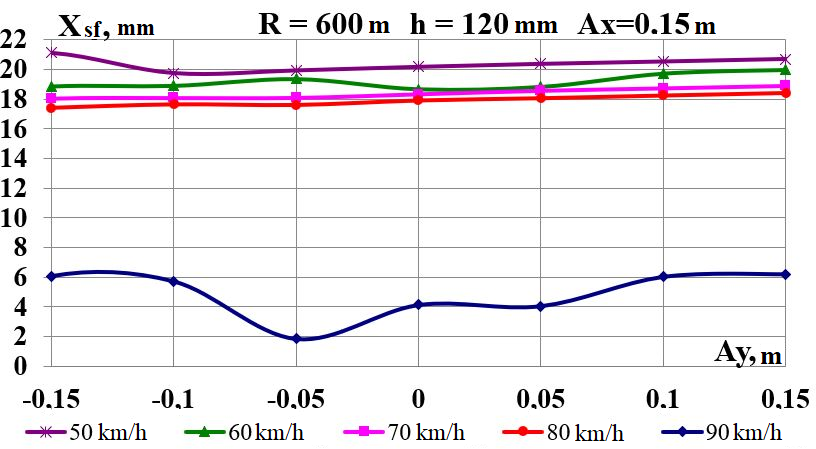
The
simultaneous displacement of the mass center along the axes
 is considered for
in the range from –0.15
to 0.15 m and
is considered for
in the range from –0.15
to 0.15 m and
 m (Fig. 7) [11].
a
b
c
d
e
f
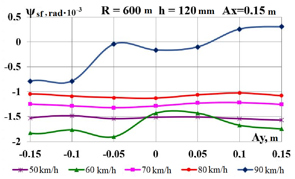
Fig
7. Graphs
of
dependence
on
simultaneous
load
displacement
in
the
longitudinal
and
transverse
direction:
a,
b
– wear factor; c,
d
– directional force acting from the rail side on the wheel;
e,
f
– hunting of the wheel set
a
b
c
d
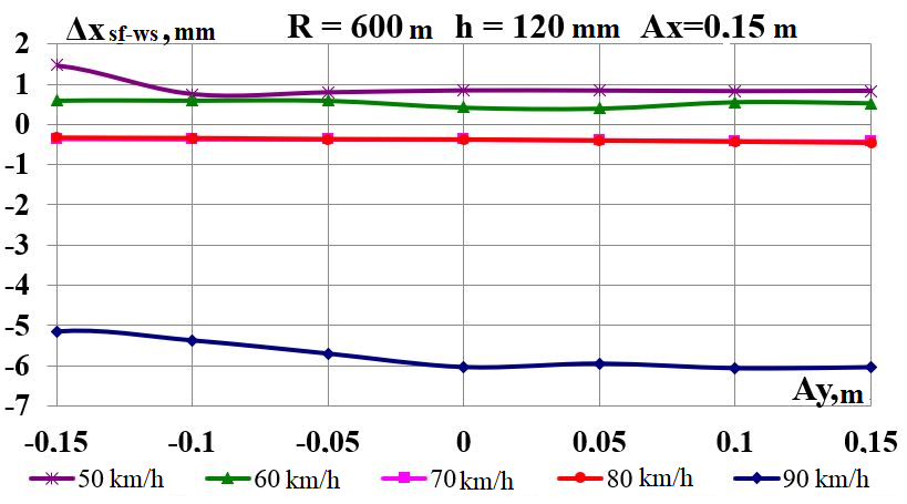
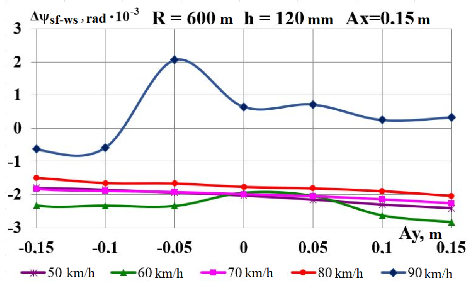
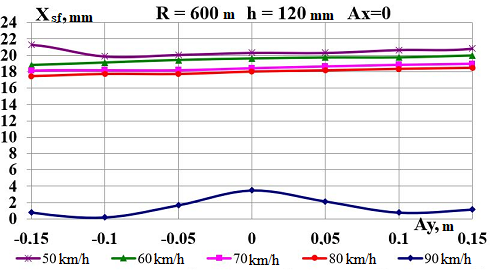
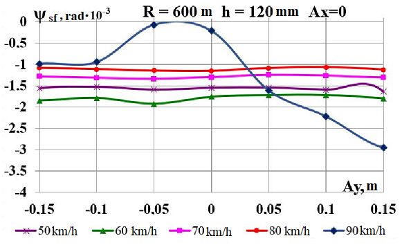
Fig.
8. Graphs
of dependence
on load
displacement in
the longitudinal
and transverse
direction:
а
–
lozenging
of side frames of the front bogie;
b
–
hunting
of the left side frame of the front bogie;
c
–
mutual
longitudinal displacement of side frame and axle box of the front
wheel set;
d
–
mutual
hunting of the bogie left side frame relative to the front wheel set
In case of
simultaneous longitudinal and transverse displacement, a significant
increase in the wheel set hunting angles
also occurs due to significant
longitudinal mutual displacements of the side frame and the axle box
of the front wheel set
(Fig. 8, c)
and the hunting of the bogie left side frame relative to the front
wheel set through the shift of the boxes in the side frame openings
(Fig. 8, d).
Unlike indicators
,
that are almost unchanged at simultaneous
longitudinal and transverse displacement, the values of the
indicators
are much lower.
The Rolling
Stock Dynamic and Strength Research Laboratory of DNURT conducted
dynamic (running) tests of the experimental train in order to
determine the dynamic load of the wheel-rail contact and the
indicators characterizing the wear of the wheel set flanges and the
rail side faces, for the most likely operational deviations from
nominal ones in the dimensions of the carriage elements in the range
of speeds 30-70 km/h. There were tested the freight flat cars of
model 12-532 on three-piece bogie of model 18-100, having different
state of carriage chassis, which to some extent could affect the
wear of wheels and rails. For conducting
the tests, there
was formed
an experimental
train consisting
of a
car-laboratory,
testes flat cars
and ChS-2
electric
locomotive.
To obtain reliable information on the
effect of variations in the dimensions of the chassis elements on
the magnitude of the dynamic loading of the wheel-rail contact, all
stages of the tests were performed on one section of the joint track
[8].
We tested
three loaded gondola cars with the following features in the
carriage chassis dimensions:
1) Gondola
No. 1, which had
6 mm difference of sideframe bases of one of the bogies (2 184.5 and
2 190.5 mm);
2) Gondola
No. 2, which
had 3 mm
deviation in
the wheel
diameters of
one wheel
set (926 and
923 mm);
3) Gondola
No. 3, which
had the
minimum
deviations in
the dimensions
of the
carriage chassis
elements from
the nominal
and was
taken as
a standard
car.
During
the dynamic
testing on
the experimental
gondola, the
following values
were recorded:
frame forces
for wheel
sets; dynamic
increments of
the vertical
forces acting
on the
wheel set
boxes;
longitudinal and
horizontal
transverse
displacement of
the boxes
relative to
the bogie
side frames;
horizontal
transverse
acceleration of
boxes; bolster
hunting angles
relative to
the body;
the value
of lozenging
of bogie side frames. During
the tests, we used the sensors of displacement and bogie side frame
lozenging.
Fig.
9, a
shows the
general view
of one
of the
axlebox mounts
of the
tested cars
equipped with
an acceleration
sensor and
two small
displacement
sensors, and
Fig. 9, b
shows the
tested bogie
of the
3rd standard
car, with
installed
«in-line»
camcorders, a
curve entry
sensor, attached
to the
box cover,
small and
large
displacement
sensors and
an acceleration
sensor.
а
– a
б
– b
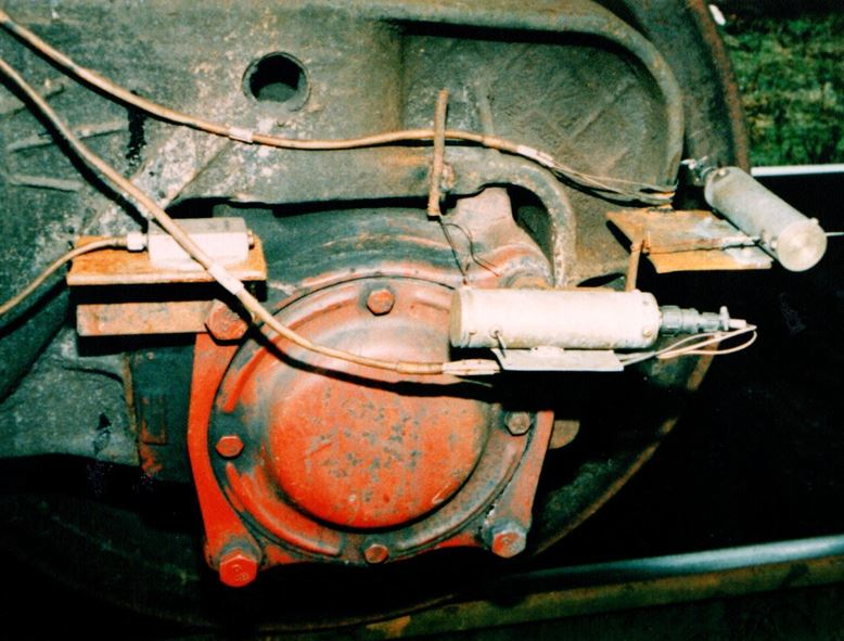
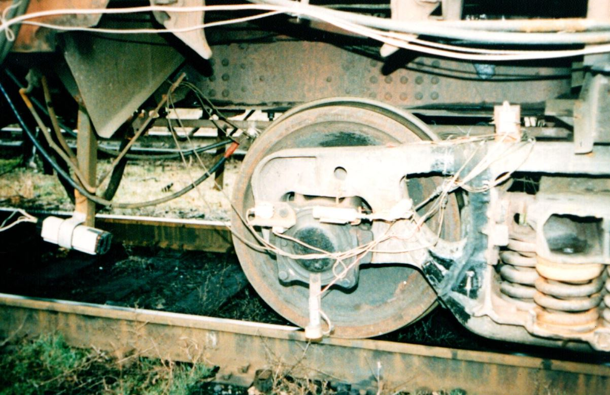
Fig. 9. Equipment
of tested cars with measuring equipment:
а
–
axlebox mount of
the tested car with an acceleration and small displacement sensors;
b
–
look of the tested
standard car bogie;
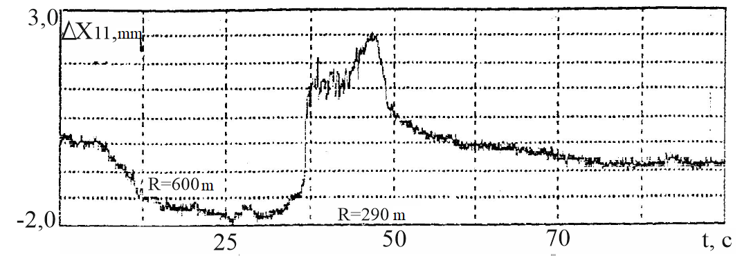
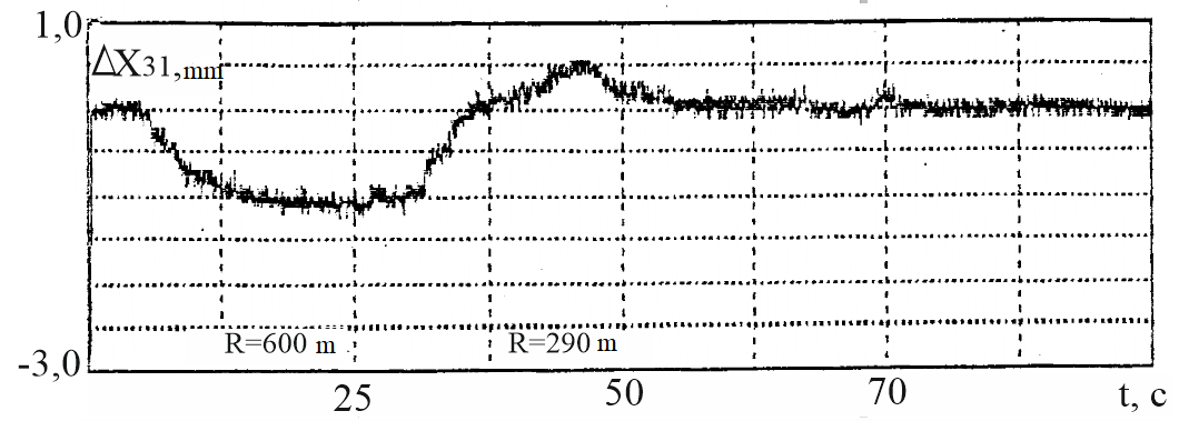
Fig. 10 shows the printouts of
the recorded changes of the longitudinal displacements of the first
wheel set axlebox mount relative to the side frames and lozenging of
the first bogie side frames of the first and third cars during the
movement of the tested train at a speed of 70 km/h. The output value
of the total longitudinal clearance of the box in the box opening
was 16 mm. The scale time (horizontally) is selected so that the
graphs display the records for the entire tested section. At the
printing time of 100 seconds, the graphics correspond to
approximately two kilometres, run by the experimental train along
the section, including a straight line, a curve with 600 m
radius, a short line between curves, a curve with 290 m radius and
a straight line. From these records it is clear that entering
into the curve with 290 m radius has a striking character.
a
b
c
d
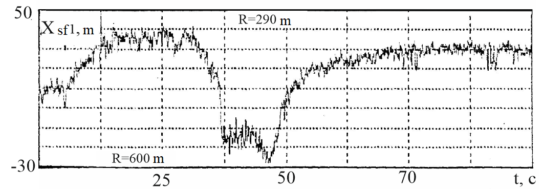
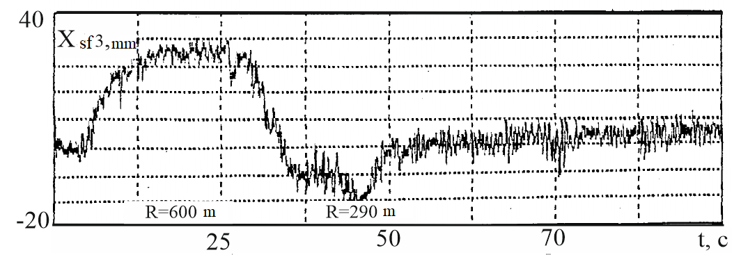
Fig. 10. Variances
records:
a,
b –
longitudinal displacements of axle boxes of the first wheel set
relative
to the first bogie side frame of the first and third
cars respectively;
c,
d –
lozenging of the first bogie side frames of the first and third cars
respectively
The
longitudinal displacement of the axle boxes relative to the side
frames (Fig. 10, a, c)
is relatively small, their double amplitude does not exceed 5
mm. Moving during the lozenging of the side frames (Fig. 10, b,
d) have rather large values, their
amplitude reaches 40 mm. The recordings of displacements of the
axlebox mounts and lozenging of side frames show the displacements
that correspond to the break of the frictional forces during the car
negotiation into a curve with 290 m radius. Based on the processing
of the test results, it has been established that the magnitude of
the longitudinal displacements of the axlebox mounts
increase slightly with increasing
velocity. The largest values
 did not exceed 3-4 mm for the first car,
regardless of the radius of the curve. For the second car during
the movement in the curve
did not exceed 3-4 mm for the first car,
regardless of the radius of the curve. For the second car during
the movement in the curve
 m the greatest values
 did not exceed 2-3 mm, and in the curve
m – 1-1.5 mm. For the third car, the
values
did not exceed 2-3 mm, and in the curve
m – 1-1.5 mm. For the third car, the
values
 in the curve
m did
not exceed
3.5 mm, and
in the
curve
m – 2-3 mm.
For comparison:
the longitudinal
displacement of
the boxes
relative to
the flat
car side
frames in
the curve
m according
to the
results of
the calculations
was 0.5-2
mm, and
lozenging of bogie side frames 17-22
mm in
the velocity
interval
km/h
for all
variants of
the load
gravity center
displacement.
Somewhat lower values of the parameters
can be explained by the larger truck-center spacing.
in the curve
m did
not exceed
3.5 mm, and
in the
curve
m – 2-3 mm.
For comparison:
the longitudinal
displacement of
the boxes
relative to
the flat
car side
frames in
the curve
m according
to the
results of
the calculations
was 0.5-2
mm, and
lozenging of bogie side frames 17-22
mm in
the velocity
interval
km/h
for all
variants of
the load
gravity center
displacement.
Somewhat lower values of the parameters
can be explained by the larger truck-center spacing.
Taking into
account the fact that the experimental train for conducting dynamic
(running) tests was formed from the gondola cars of the model
12-532, and the theoretical calculations are given for the flat car
of the model 13-401, we note that the obtained results have a rather
high coincidence. The results
of calculations,
as well
as the
data of
experiments,
indicate that
the wear
indicators in
these cases,
in general,
grow with
increasing
speed. The
value of
wear indicators
for other
equal conditions
during the
movement of
cars in
the curve
with 300 m
radius is
higher than
during movement
in the
curve with
600 m radius.
Originality
and practical value
In the
process of research, we obtained the following scientific and
practical results:
– Mathematical
model of
coupling of
five freight
cars was
used to
study the
effect of
the loading
characteristics
of the
flat car
on the
value of
the wheel-rail
pair wear
factor;
– There
are assessed
such indicators
as the
wear factor,
the directional
force, and
hunting of
the wheel
set of
freight rolling
stock in
the event
of load
gravity centre
displacement
when moving
along curved
sections of
the railway
track;
– To
establish the
possible cause
of intensive
wear of
the wheels
and rails,
the following
parameters were
analysed:
lozenging of
front bogie
side frames;
hunting of
the left
side frame
of the
front bogie;
mutual
longitudinal
movement of
the side
frame and
axle box
of the
front wheel
set; mutual
hunting of
the left
side frame
of the
bogie relative
to the
front wheel
set;
– The
influence of speed on the mentioned indicators is investigated.
Conclusions
Based on the
analysis of theoretical studies conducted on the example of a flat
car, the following conclusions can be drawn:
– Lozenging
of bogie
side frames
of a
flat car
in the
range of
speeds of
50-80 km/h
does not
affect the
factor of
wear of
wheels and
rails both
at longitudinal
and transverse
displacement of
the load
mass center;
– Longitudinal
displacement of
load on
flat cars
does not
cause an
increase in
the studied
parameters;
– The
most probable reason for the intensive wear of wheels and rails
under the same conditions of motion is the temporary change in the
running characteristics of some carriages, namely, an increased
angle of climbing of individual wheels due to the bogie rotation
relative to the track or due to the rotation of the wheel set axle
due to the box shift in the bogie side frame openings.
LIST OF REFERENCE LINKS
Бороненко,
Ю. П. Инновации в тележках грузовых
вагонов: реальность и перспективы / Ю.
П. Бороненко, Е. А. Рудакова, А. М. Орлова
// Наука и транспорт.
– 2009. – № S. – С. 14–17.
Данович, В.
Д. Колебания в горизонтальной плоскости
4-осн. платформы с несимметрично
расположенным тяжеловесным грузом /
В. Д. Данович, П. С. Анисимов // Вестн.
ВНИИЖТ. – 1989. – № 3. – С. 5–9.
Данович, В.
Д. Математическая модель пространственных
колебаний сцепа пяти вагонов, движущихся
по прямолинейному участку пути / В. Д.
Данович, А. А. Малышева // Транспорт.
Нагруженность и прочность подвижного
состава : сб. науч. тр.
/ Днепропетр. гос. техн.
ун-т ж.-д. трансп. – Днепропетровск,
1998. – С. 62–69.
Данович, В.
Д. Пространственные колебания вагонов
на инерционном основании : дис. … д-ра
техн. наук : 05.22.07 / Данович
Виктор Данилович ;
Днепропетр. ин-т инж. ж.-д. трансп.
– Днепропетровск, 1981.
– 465 с.
Знос коліс
та рейок при нерівномірному завантаженні
піввагонів / Анжела О. Швець, О. М.
Болотов, Л. С. Сапарова, Анжеліка О.
Швець // Вісн. сертифікації залізн.
трансп. – 2019. – № 1. – С. 4–17.
Определение
показателей безопасности движения
платформ с порожним автопоездом / А.
В. Шатунов, В. В. Соборницкая, Е. Н. Ковтун,
О. М. Маркова // Транспорт : сб.
науч. тр. / Днепропетр.
гос. техн. ун-т ж.-д. трансп. –
Днепропетровск, 2001. – Вып. 7. – С. 116–120.
Петров, Г.
И. Модернизация грузовых тележек:
установка поперечной связи / Г. И.
Петров, Н. Ю. Черняев, М. А. Мещеряков //
Мир транспорта. – 2015. – № 5. – С. 58–62.
Разработка
рекомендаций по снижению износа колес
и рельсов за счет снижения сил
динамического взаимодействия
железнодорожных экипажей и пути с
учетом стационарных и нестационарных
режимов движения. В 3 т. Т. 3. Натурные
исследования факторов, влияющих на
повышенный износ рельсов и гребней
колес грузовых вагонов : отчет о НИР
(заключ.) : 91.134.95.97/379.95.97 ЦТех / Днепропетр.
нац. ун-т ж. д. трансп. им. акад. В. Лазаряна
; рук. Блохин Е. П., Пшинько А. Н. ; исп.:
Данович В. Д. [и др.].
– Днепропетровск, 1998. –
190 с. – № ГР 0196U023134. –
Инв. № 416(III).
Совершенствование
конструкции тележек грузовых вагонов
с целью снижения износа гребней колес
и рельсов / И. Э. Мартынов, В. Г. Маслиев,
С. Д. Мокроусов, В. П. Щербаков, В. И.
Нестеренко // Зб. наук.
пр. Укр.
держ. акад.
залізн. трансп. – 2013. –
Вип. 139. – С. 25–34.
Теоретическая
оценка динамических качеств платформ,
загруженных автопоездом с грузом / А.
В. Шатунов, В. В. Соборницкая, Е. Н. Ковтун,
О. М. Маркова // Транспорт : сб.
науч. тр. /
Днепропетр. гос. техн. ун-т
ж.-д. трансп. – Днепропетровск,
2000. – Вып. 3. – С. 21–27.
Технические
условия размещения и крепления грузов.
Приложение 3 к Соглашению о
международном железнодорожном грузовом
сообщении (СМГС). – Київ
: Девольта, 2011.
– Т. 1. – 436
с.
Шатунов, А.
В. Нагруженность
сцепа из двух платформ при ресурсосберегающем
способе транспортировки длинномерных
грузов : автореф. дис.
… канд. техн. наук : 05.22.07 /
Шатунов Александр Васильевич ;
Днепропетр. ин-т инж. ж.-д. трансп. –
Днепропетровск, 1992.
– 17 с.
Швець,
А. О. Вплив поздовжнього та поперечного
зміщення центру ваги вантажу в піввагонах
на їх динамічні показники / А. О. Швець
// Наука та прогрес
транспорту. – 2018. – № 5
(77). – С. 115–128.
doi: 10.15802/stp2018/146432
Ashtiani,
H. Influence of friction wedge characteristics on lateral response
and hunting of freight cars with three-piece bogies / H. Ashtiani,
S. Rakheja, A. K. W. Ahmed // Proceedings of the Institution of
Mechanical Engineers, Part F: Journal of Rail and Rapid Transit. –
2017. – Vol. 231. – Iss. 8. – P. 877–891. doi:
10.1177/0954409716647095
Effect
of the state of car running gears and railway track on wheel and
rail wear / E. P. Blokhin, O. M. Pshinko, V. D. Danovich, M. L.
Korotenko // Railway Bogies and Running Gears : Proc. of the 4th
Intern. Conf. / Technical University of Budapest. – Budapest,
1998. – P. 313–323.
Effects
of profile wear on wheel-rail contact conditions and dynamic
interaction of vehicle and turnout / J. Xu, P. Wang, L. Wang, R.
Chen // Advances in Mechanical Engineering. – 2016. – Vol. 8. –
Iss. 1. – P. 1–14. doi:
10.1177/1687814015623696
Generation
mechanism and remedy method of rail corrugation at a sharp curved
metro track with Vanguard fasteners [Electronic resource]/ B. W.
Wu, G. X. Chen, J. Z. Lu, Q. Zhu, X. Kang // Journal of Low
Frequency Noise Vibration and Active Control. – 2019. –
Available at:
https://journals.sagepub.com/doi/10.1177/1461348419845992
– Title from the screen. – Accessed :
26.06.2019.
doi:
10.1177/1461348419845992
Lack,
T. Freight car bogie properties analysis by means of simulation
computations / T. Lack, J. Gerlici, M. Manurova //
Manufacturing Technology. – 2016. – Vol. 16. – Iss. 4. – P.
733–739.
Light
weight freight rolling stock bogie frame: Design methodology
validated with field oscillation trials / S. Shukla, U. Kumar,
S. K. Sharma, P. Gupta, A. Kumar // International Journal of
Vehicle Structures and Systems.
– 2017. – Vol. 9. – Iss. 4. – P. 245–250. doi:
10.4273/ijvss.9.4.10
Modeling,
simulation and applications of
longitudinal train dynamics / C.
Cole, M.
Spiryagin, Q.
Wu, Y.
Q. Sun //
Vehicle System Dynamics.
– 2017. –
Vol. 55. – Іss.
10. – P.
1498–1571.
doi:10.1080/00423114.2017.1330484
Shatunov,
O. V. Study of dynamic indicators of flat car with load centre
shift / O. V.
Shatunov, A. O. Shvets // Наука та
прогрес транспорту. –
2019. – № 2 (80). – С. 127–143.
doi: 10.15802/stp2019/165160
Wu,
Q. Longitudinal
train dynamics: an
overview / Q.
Wu, M. Spiryagin,
C. Cole //
Vehicle System Dynamics.
– 2016. –
Vol. 54. –
Іss. 12.
– P. 1688–1714.
doi: 10.1080/00423114.2016.1228988
Ye,
Y. Small-amplitude hunting diagnosis method for high-speed trains
based on the bogie frame’s lateral–longitudinal–vertical data
fusion, independent mode function reconstruction and linear local
tangent space alignment [Electronic resource]/ Y. Ye, J. Ning //
Proceedings of the Institution of Mechanical Engineers, Part F:
Journal of Rail and Rapid Transit. – 2019. – Available at:
https://journals.sagepub.com/doi/10.1177/0954409718825412 – Title
from the screen. – Accessed : 26.06.2019.
doi:
10.1177/0954409718825412
О.
В. Шатунов1*,
А. О. Швець2*,
О. А. Кирильчук3*,
А. О. Швець4*
1*Каф.
«Вагони та вагонне господарство»,
Дніпровський національний університет
залізничного
транспорту імені академіка
В. Лазаряна, вул. Лазаряна, 2, Дніпро,
Україна, 49010, тел.
+38 (067) 953 60 14,
ел. пошта shatunov220648@gmail.com,
ORCID 0000-0002-1115-0093
2*Каф. «Теоретична
та будівельна механіка», Дніпровський
національний університет залізничного
транспорту імені академіка В. Лазаряна,
вул. Лазаряна, 2, Дніпро, Україна, 49010,
тел. +38 (050) 214 14 19,
ел. пошта
angela.shvets69@gmail.com, ORCID 0000-0002-8469-3902
3*Каф.
«Вагони та вагонне господарство»,
Дніпровський національний університет
залізничного
транспорту імені академіка
В. Лазаряна, вул. Лазаряна, 2, Дніпро,
Україна, 49010, тел. +38 (056) 776 82 27,
ел. пошта
e-mail o.a.kirilchuk@gmail.com, ORCID 0000-0002-0565-1692
4*Каф.
«Вагони та вагонне господарство»,
Дніпровський національний університет
залізничного
транспорту імені академіка
В. Лазаряна, вул. Лазаряна, 2, Дніпро,
Україна, 49010, тел.
+38 (095) 235 19
67,
ел. пошта
angela_Shvets@ua.fm, ORCID 0000-0002-0717-2521
ДОСЛІДЖЕННЯ
ЗНОСУ КОЛІС ТА РЕЙОК
ЗА НЕСИМЕТРИЧНОго
ЗАВАНТАЖЕННя
ПЛАТФОРМИ
Мета.
У науковій роботі потрібно провести
визначення впливу несиметричного
завантаження вагона-платформи на
величину фактора зносу пари «колесо-рейка»
в разі зміни параметрів, що мають місце
в експлуатації. Методика.
Динамічну навантаженість вагона-платформи
моделі 13–401 з типовими трьохелементними
візками досліджено з використанням
моделі просторових коливань зчепу з
п’яти вагонів за допомогою математичного
й комп’ютерного моделювання. Теоретичні
розрахунки виконано для найбільш
небезпечних ділянок залізничної
колії-кривих малого й середнього радіуса
в інтервалі допустимих швидкостей
руху. Результати.
Проаналізовано показники
зносу коліс рухомого складу й рейок на
прикладі вагонів-платформ за наявності
поздовжнього й поперечного зміщення
центра мас вантажу відносно центра
симетрії вагона. Для отримання інформації
про вплив допустимих відхилень
розташування вантажу у вагоні на
величину динамічної навантаженості
контакту «колесо-рейка» виконано
теоретичні дослідження просторових
коливань рейкового екіпажу та його
взаємодії з колією. Наукова
новизна. Для визначення
зносу пари «колесо-рейка» досліджено
вплив зміщення у двох напрямках від
центральної осі симетрії центра мас
вантажу з огляду на величину швидкості
руху по кривих ділянках колії малого
й середнього радіуса із застосуванням
математичної моделі зчепу з п’яти
вантажних вагонів.
Практична значимість.
У результаті проведених теоретичних
досліджень оцінено такі показники, як
фактор зносу, напрямлена сила й виляння
колісної пари вантажного рухомого
складу в разі зміщення центра мас
вантажу під час руху по криволінійних
ділянках залізничної колії. Для
встановлення ймовірної причини
інтенсивного зносу коліс і рейок
проаналізовано параметри: забігання
бокових рам переднього візка; виляння
лівої бокової рами переднього візка;
взаємне поздовжнє переміщення бокової
рами й буксового вузла передньої
колісної пари; взаємне виляння лівої
бокової рами візка відносно передньої
колісної пари.
Ключові
слова: вантаж; вагон-платформа;
забігання бокових рам візка; зміщення
центра тяжіння вантажу; кут виляння
колісної пари; швидкість руху; фактор
зносу
А.
В. Шатунов1*,
А. А. Швец2*,
О. А. кирильчук3*,
А. А. Швец4*
1*Каф.
«Вагоны и вагонное хозяйство», Днипровский
национальный университет железнодорожного
транспорта имени академика В. Лазаряна,
ул. Лазаряна, 2, Днипро,
Украина, 49010, тел. +38 (067) 953 60 14,
эл. почта
shatunov220648@gmail.com, ORCID 0000-0002-1115-0093
2*Каф.
«Теоретическая и строительная механика»,
Днипровский национальный университет
железнодорожного
транспорта имени
академика В. Лазаряна, ул. Лазаряна, 2,
Днипро, Украина, 49010, тел.
+38 (050) 214 14 19,
эл. почта angela.shvets69@gmail.com,
ORCID 0000-0002-8469-3902
3*Каф.
«Вагоны и вагонное хозяйство», Днипровский
национальный университет железнодорожного
транспорта имени академика В. Лазаряна,
ул. Лазаряна, 2, Днипро, Украина, 49010, тел.
+38 (056) 776 82 27,
эл.
почта e-mail o.a.kirilchuk@gmail.com,
ORCID 0000-0002-0565-1692
4*Каф.
«Вагоны и вагонное хозяйство»,
Днипровский национальный университет
железнодорожного
транспорта имени
академика В. Лазаряна, ул. Лазаряна, 2,
Днипро, Украина, 49010, тел. +38 (095) 235 19 67,
эл. почта angela_Shvets@ua.fm, ORCID 0000-0002-0717-2521
ИССЛЕДОВАНИЕ
ИЗНОСА КОЛЕС И рельсов
при несимметричной
загрузке ПЛАТФОРМЫ
Цель.
В научной работе нужно провести
определение влияния несимметричной
загрузки вагона-платформы на величину
фактора износа пары «колесо–рельс»
при изменении параметров, имеющих место
в эксплуатации. Методика.
Динамическую нагруженность вагона-платформы
модели 13–401 с типовыми трехэлементными
тележками исследовано с использованием
модели пространственных колебаний
сцепа из пяти вагонов с помощью
математического и компьютерного
моделирования. Теоретические расчеты
выполнены для наиболее опасных участков
железнодорожного пути-кривых малого
и среднего радиуса в интервале допустимых
скоростей движения. Результаты.
Проанализированы показатели износа
колес подвижного состава и рельсов на
примере вагонов-платформ при наличии
продольного и поперечного смещения
центра масс груза относительно центра
симметрии вагона. Для получения
информации о влиянии допустимых
отклонений расположения груза в вагоне
на величину динамической нагруженности
контакта «колесо–рельс» выполнены
теоретические исследования пространственных
колебаний рельсового экипажа и его
взаимодействия с колеей. Научная
новизна. Для определения
износа пары «колесо-рельс» исследовано
влияние смещения в двух направлениях
от центральной оси симметрии центра
тяжести груза с учетом величины скорости
движения по кривых участках пути малого
и среднего радиуса с применением
математической модели сцепа из пяти
грузовых вагонов. Практическая
значимость. В результате
проведенных теоретических исследований
оценены такие показатели, как фактор
износа, направленная сила и виляние
колесной пары грузового подвижного
состава в случае смещения центра тяжести
груза при движении по криволинейным
участкам железнодорожного пути. Для
установления возможной причины
интенсивного износа колес и рельсов
проанализированы параметры: забегание
боковых рам передней тележки; виляние
левой боковой рамы передней тележки;
взаимное продольное перемещение боковой
рамы и буксового узла передней колесной
пары; взаимное виляние левой боковой
рамы тележки относительно передней
колесной пары.
Ключевые
слова: груз; вагон-платформа;
забегание боковых рам тележки; смещение
центра тяжести груза; угол виляния
колесной пары; скорость движения; фактор
износа
REFERENCES
Boronenko,
Y. P., Rudakova, Y. A., & Orlova, A. M. (2009). Innovatsii v
telezhkakh gruzovykh vagonov: realnost i perspektivy. Nauka
i transport, S,
14-17. (in
Russian)
Danovich,
V. D., & Anisimov, P. S. (1989). Kolebaniya v gorizontalnoy
ploskosti 4-osn. platformy s nesimmetrichno raspolozhennym
tyazhelovesnym gruzom. Vestnik of the
Railway Research Institute, 3, 5-9.
(in Russian)
Danovich,
V. D., & Malysheva, A. A. (1998). Mathematical Model of Spatial
Oscillations of the Coupling of Five Cars Moving Along a
Rectilinear Section of the Track.
In Transport.
Stress loading and durability of a rolling stock
(рр. 62-69).
Dnepropetrovsk.
(in Russian)
Danovich,
V. D. (1981). Spatial Cars
Oscillations in Inertia Track.
(Dysertatsiia doktora tekhnichnykh nauk). Dnepropetrovsk
Institute of Railway Transport Engineering,
Dnеpropetrovsk.
(in Russian)
Shvets,
Angela O., Bolotov, O. M., Saparova, L. S., & Shvets, Angelika
O. (2019). Wear Wheels and Rails at the Uneven Loading of Gondola
Cars. Visnyk sertyfikatsii
zaliznychnoho transportu,
1(53), 4-17.
(in Ukrainian)
Shatunov,
A. V., Sobornitskaya, V. V., Kovtun, E. N., & Markova, O. M.
(2001). Opredelenie pokazatelej bezopasnosti dvizheniya platform s
porozhnim avtopoezdom. Transport,
7, 116-120. (in Russian)
Petrov,
G. I., Chernyaev, N. Y., & Meshcheryakov, M. A. (2015).
Modernization of Cargo Bogies: Mounting of a Transverse Connection
Assembly. Mir transporta.
5, 58-62. (in Russian)
Blokhin,
E. P., Pshinko, O. M., & Danovich, V. D. (1998). Razrabotka
rekomendatsiy po snizheniyu iznosa koles i relsov za schet
snizheniya sil dinamicheskogo vzaimodeystviya zheleznodorozhnykh
ekipazhey i puti s uchetom statsionarnykh i nestatsionarnykh
rezhimov dvizheniya (Vol. 1-3).
Dnеpropetrovsk
National University of Railway Transport named after Academician V.
Lazaryan,
Dnеpropetrovsk.
(in Russian)
Martynov,
I. E., Masliev, V. G., Mokrousov, S. D., Nesterenko, V. I., &
Shcherbakov, V. P. (2013). Improved design cargo trucks-cars out to
prevent wear paddle wheels and rails. Zbirnyk naukovykh
prats Ukrainskoi derzhavnoi akademii zaliznychnoho transportu,
139,
25-34. (in
Russian)
Shatunov,
A. V., Sobornitskaya, V. V., Kovtun, E. N., & Markova, O. M.
(2000). Teoreticheskaya otsenka dinamicheskikh kachestv platform,
zagruzhennykh avtopoezdom s gruzom. Transport,
3, 21-27. (in Russian)
Tekhnicheskie
usloviya razmeshcheniya i krepleniya gruzov.
Prilozhenie 3 k Soglasheniyu o
mezhdunarodnom zheleznodorozhnom gruzovom soobshchenii (SMGS).
(2011). Kyiv:
Devolta. (in
Russian)
Shatunov,
A. V.
(1992). Nagruzhennost
stsepa
iz
dvukh
platform
pri
resursosberegayushchem
sposobe
transportirovki
dlinnomernykh
gruzov.
(Avtoreferat dysertatsii kandydata tekhnichnykh nauk).
Dnepropetrovsk Institute of
Railway Transport Engineering, Dnеpropetrovsk.
(in Russian)
Shvets,
A. O. (2018). Influence of the longitudinal and transverse
displacement of the cargo gravity center in gondola cars on their
dynamic indicators. Science
and Transport Progress,
5(77),
115-128.
doi: 10.15802/stp2018/146432
(in Ukrainian)
Ashtiani,
H., Rakheja, S., & Ahmed, A. K. W. (2017). Influence of
friction wedge characteristics on lateral response and hunting of
freight cars with three-piece bogies. Proceedings
of the Institution of Mechanical Engineers, Part F: Journal of Rail
and Rapid Transit, 231(8),
877-891. doi: 10.1177/0954409716647095 (in
English)
Blokhin,
E. P., Pshinko, O. M., Danovich, V. D., & Korotenko,
M. L. (1998). Effect of the state of car running gears and railway
track on wheel and rail wear. Railway
Bogies and Running Gears: Proceedings of the 4th International
Conference (рр.
313-323).
Budapest. (in English)
Xu,
J., Wang, P., Wang, L., & Chen, R. (2016). Effects of profile
wear on wheel-rail contact conditions and dynamic interaction of
vehicle and turnout. Advances in
Mechanical Engineering, 8(1),
1-14. doi:
10.1177/1687814015623696 (in English)
Wu,
B. W., Chen, G. X.,
Lu, J. Z., Zhu, Q., & Kang, X.
(2019). Generation mechanism and remedy method of rail corrugation
at a sharp curved metro track with Vanguard fasteners. Journal
of Low Frequency Noise Vibration and Active Control.
doi: 10.1177/1461348419845992 (in English)
Lack,
T., Gerlici, J., & Manurova, M. (2016). Freight car bogie
properties analysis by means of simulation computations.
Manufacturing Technology,
16(4),
733-739. (in English)
Shukla,
S., Kumar, U., Sharma, S. K., Gupta, P.,
& Kumar, A. (2017). Light weight
freight rolling stock bogie frame: Design methodology validated
with field oscillation trials. International
Journal of Vehicle Structures and Systems,
9(4),
245-250. doi: 10.4273/ijvss.9.4.10 (in English)
Cole,
C., Spiryagin, M., Wu, Q., & Sun, Y. Q. (2017). Modeling,
simulation and applications of longitudinal train dynamics. Vehicle
System Dynamics, 55(10), 1498-1571.
doi:
10.1080/00423114.2017.1330484
(in English)
Shatunov,
O. V., & Shvets, A. О. (2019). Study
of dynamic indicators of flat car with load centre shift. Science
and Transport Progress,
2(80), 127-143.
doi: 10.15802/stp2019/165160
(in English)
Wu,
Q., Spiryagin, M., & Cole, C. (2016). Longitudinal train
dynamics: an overview. Vehicle System
Dynamics, 54(12), 1688-1714. doi:
10.1080/00423114.2016.1228988 (in
English)
Ye,
Y., & Ning, J. (2019). Small-amplitude hunting diagnosis method
for high-speed trains based on the bogie frame’s
lateral–longitudinal–vertical data fusion, independent mode
function reconstruction and linear local tangent space alignment.
Proceedings of the Institution of
Mechanical Engineers, Part
F: Journal of Rail and Rapid Transit.
doi: 10.1177/0954409718825412 (in English)
Received:
March 11,
2019
Accepted:
July 08,
2019