ISSN
2307–3489 (Print), ІSSN
2307–6666
(Online)
Наука
та прогрес транспорту. Вісник
Дніпропетровського
національного університету залізничного
транспорту, 2019,
№ 2 (80)
рухомий
склад залізниць і тяга поїздів
UDC
629.463.62.015
O.
V. Shatunov1*,
A. O. shvets2*
1*Dep.
«Cars and Car Facilities»,
Dnipro National University of Railway Transport named after
Academician V. Lazaryan,
La-zaryan St., 2, Dnipro, Ukraine,
49010, tel. +38 (067) 953 60 14, e-mail shatunov220648@gmail.com,
ORCID 0000-0002-1115-0093
2*Dep.
«Theoretical and Structural Mechanics»,
Dnipro National University of Railway Transport named after
Academician
V. Lazaryan, Lazaryan St., 2, Dnipro, Ukraine, 49010,
tel. +38 (050) 214 14 19, e-mail angela_Shvets@ua.fm,
ORCID
0000-0002-8469-3902
STUDY
OF DYNAMIC INDICATORS OF FLAT
WAGON WITH LOAD
CENTRE SHIFT
Purpose.
The article deals with the determining the
influence of the longitudinal and lateral shift of gravity centre of
the heavy load on the flat wagons, taking into account the travel
speed based on the main dynamic indicators – the maximum
coefficients of the dynamic supplement of spring-suspended and
unsprung parts, the maximum ratio of frame force to static axle load,
the wheel derailment safety factor.
Methodology.
The study was carried out using the method of mathematical and
computer simulation of the dynamic loading of flat
wagons based on the model of spatial oscillations of five coupled
wagons and the software complex developed in the branch research
laboratory of the rolling stock dynamics and strength (BRL RSDS).
Theoretical studies were carried out during the movement of the model
13-401 flat
wagon on typical 18-100 bogies with speeds in the range from 50
to 90 km/h in curves with radii of 350 and 600 m, with 130 and 120 mm
canting, respectively. Findings. The
paper presents the analysis of theoretical studies of the rolling
stock dynamics on the example of flat wagons. The calculations were
carried out using an application software package.
In the course of performing theoretical studies and after simulation,
taking into account the processes of oscillation of the flat wagon
and load in the presence of longitudinal and lateral shift of its
gravity centre, the dependences of the main dynamic indicators were
obtained with regard to the magnitude of the travel speed.
Originality.
Using the mathematical model of the five coupled wagons, the effect
of shift in two directions from the central symmetry axis of the
heavy load centre was studied with regard to the travel speed along
the curved track of small and medium radius in order to determine the
dynamic loading of the flat wagon. Practical
value. As a result of the above
theoretical studies, the recommendations on the maximum possible
values of the centre shift of heavy loads during their transportation
on flat wagons are substantiated and proposed.
Keywords:
load; flat
wagon; dynamic indicators; curved track; longitudinal and lateral
load; centre shift; travel speed
Introduction
The process of integrating the
railway industry of Ukraine into the European transport system is
one of the urgent problems of today. Its solution is connected with
the formation of a network of international transport corridors on
the territory of Ukraine, the reconstruction of the main railway
lines connecting the Europe and Ukraine, the organization of
high-speed train traffic [10].
In addition, one of the key
issues of transport policy, which is associated with perspectives of
sustainable development of the transport industry in Ukraine, is the
promotion of combined transport. This technology should be in line
with international standards, the main criteria of which are: route
speed, schedule accuracy and cargo safety. Increased speed and
frequency of transportation would accelerate the introduction of a
combined cargo transportation system, including by international
transport corridors. Thus, improvement of speed characteristics of
rolling stock becomes almost the most important task for increasing
the competitiveness of rail transport in mixed traffic systems.
One of the
main obstacles to a significant increase in the velocity of combined
transport is the dynamic properties of the rolling stock. At the
same time, the main characteristics of the rolling stock are being
constantly improved by the producing factories, with the changing of
the range of goods. Among the
heavy loads
transported on
flat wagons,
the more
common is
becoming the
equipment with
asymmetrical
centre of
gravity, which
requires train
speed
limitation. This
causes a reduction in the throughput and transportation capacity
of railways, lengthening of the equipment delivery time to the
consumer [3, 10, 18].
Purpose
Of particular
importance is the further improvement of the transportation
conditions and, in particular, the development of new scientifically
based admissible values of longitudinal and lateral load centre
shifts from the flat wagon symmetry axes. When elaborating them,
particular attention should be paid to the safety of movement, as
there may be intense fluctuations of rolling stock and large dynamic
forces. Therefore, of great interest is the study of spatial
oscillations of a flat wagon with asymmetric load, which in turn
leads to the need for the development of regional, local
(LTC) and unspecified (UTC) technical conditions, the
effect of which would be extended to enterprises serviced by one
railway [1, 3, 7, 9, 11, 12].
The purpose
of this research is
to determine the influence of the longitudinal and lateral shift of
gravity centre of the heavy load on the flat wagon, taking into
account the travel speed based on the main dynamic indicators –
the maximum coefficients of the dynamic supplement of
spring-suspended and unsprung parts, the maximum ratio of frame
force to static axle load, the wheel derailment safety factor.
Methodology
The
above problems
can be
solved
experimentally
or
theoretically.
The first method, although it is
sufficiently reliable, but expensive, requires a long time and
cannot cover all possible options of the load positioning.
Therefore, it is necessary to develop a general theoretical method
for studying the oscillation of the flat wagon with asymmetric
placement of loads of different weights, both with
spring-dissipative elements between the load and the flat wagon
body, and without them [3].
Quantitative
evaluation of
dynamic
indicators can
be obtained
by mathematic
simulation. The
wagon
calculation
scheme should
reflect the
specifics of
the wagon
interaction in
the train:
the possibility
of manifestation
of all
forms of
body
oscillations in
space, the
transmission of
longitudinal
forces in
the vertical
and horizontal
directions from
the neighboring
wagons, the
record of
the technical
condition of
individual parts
of the
wagon and
their design
features, as
well as
operating
conditions –
speed, movement
along the
straight and
curved tracks,
loading mode,
type of load,
its positioning
and fastening,
vertical and
horizontal track
irregularities [5, 8, 13, 15-22].
The
travel speed
when passing
on the
curved track
is limited
by the
lateral impact
of the
railway rolling
stock on
the track,
the lateral
acceleration
value, the
possibility of
wheel unloading
and derailment.
In connection with this, it is necessary
to study the railway vehicle oscillations while driving precisely
along the curved track.
The calculation scheme of the
flat wagon in Fig. 1 shows positive directions for all shifts and
angles of rotation, and Table 1 shows the designation of the system
bodies.
In
Table 1 through
 ,
,
 and
and
 we marked
the gravity
centre shift
of the
flat wagon
frame along
the
corresponding
axes, and
through
we marked
the gravity
centre shift
of the
flat wagon
frame along
the
corresponding
axes, and
through
 ,
,
 ,
,
 – the angles
of its
rotation
relative to
the main
central axis
of inertia.
Similar
displacements of
bolsters are
provided with
the index
– the angles
of its
rotation
relative to
the main
central axis
of inertia.
Similar
displacements of
bolsters are
provided with
the index (
( –
bogie number),
side frames –
with the
index
–
bogie number),
side frames –
with the
index
 (
( –left,
 right side
of the
wagon), wheel
sets – with
the index
right side
of the
wagon), wheel
sets – with
the index
 (
( – wheel set
number in
the bogie),
rails in
the wheel
contact points
– wheel set
number in
the bogie),
rails in
the wheel
contact points
 (movements of rails are assumed only in
two directions – along the axes
(movements of rails are assumed only in
two directions – along the axes
 and
and
 ).
Displacement of the wheels is indicated by
the index
).
Displacement of the wheels is indicated by
the index
 .
.
The
mathematical model describing the spatial oscillations of the
coupled wagons in the train (Fig. 2) is proposed in [4], of
which one
rail vehicle
is considered
as per
the most
complete
calculation
scheme (called
«zero»), and
the calculation
schemes of
neighbouring
wagons,
depending from
task setting,
are simplified
with increasing
distance from
the «zero»
vehicle on
both sides.
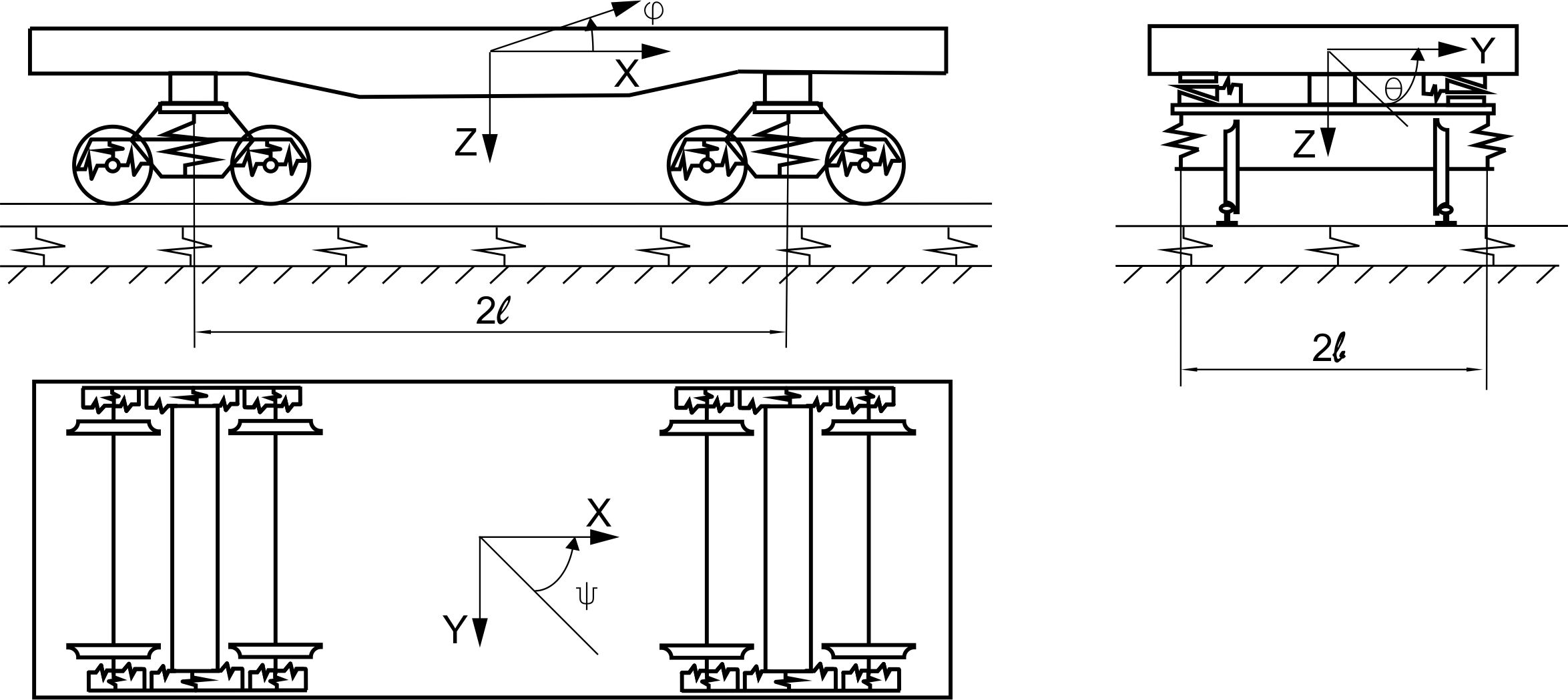
Fig. 1. Calculation
scheme of a 4-axle flat wagon
Table 1
Systems
bodies and their displacements
|
Systems
bodies
|
Displacement
|
|
|
Linear
along the axes
|
Angle
relative to axes
|
|
|

|

|

|
|
|
|
|
flat
wagon frame
|

|

|

|

|

|

|
|
bolsters
|

|

|

|

|

|

|
|
side
frames
|

|

|

|

|

|

|
|
wheel
sets
|

|

|

|

|

|

|
|
rails
|
-
|

|

|
–
|
–
|
–
|
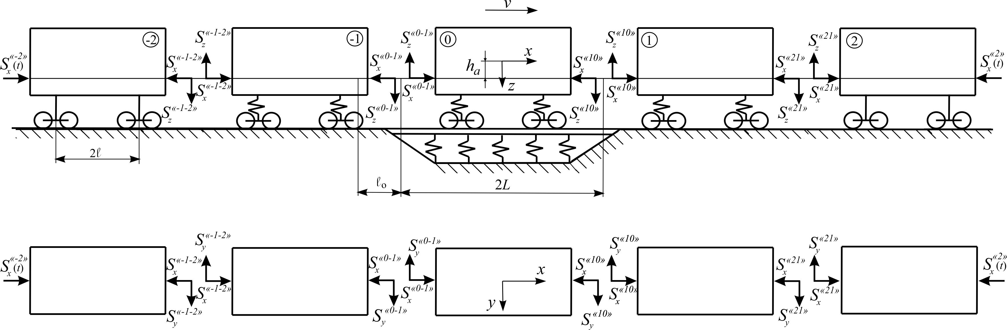
Fig. 2. Calculation
scheme of five coupled freight wagons
As a
calculation scheme of the «zero» vehicle we adopted a mechanical
system with 58 degrees of freedom [5, 17]. The following values are
adopted as generalized coordinates:


 ,
,

 ,
,

 ,
,

 ,
,

 ,
,

 ,
,

 ,
,

 ,
,

 ,
,

 ,
,

 ,
,

 ,
,

 ,
,
 .
.
Wagons, adjacent to the «zero»
one, are represented by a system with 12 degrees of freedom. The
calculation schemes describing the oscillations of these wagons
preserve the main features of freight wagon bogies – lozenging of
side frames.
In the study
of spatial oscillations of wagons neighboring with the «zero» one,
which are considered under the simplified calculation scheme, the
following assumptions are introduced. It is assumed that the wagons
have one-stage spring suspension. Each of them consists of eleven
solid bodies: a body, two bolsters, four bogie side frames and four
wheel sets. Unlike the «zero» wagon, the track under adjacent
wagons is considered to be absolutely rigid in the vertical
direction and resilient in the horizontal lateral direction. This
assumption does not lead to an increase in
the number of degrees of freedom, since the speed of the pressed
(displaced) rails in expressions for lateral forces
can be neglected.
As
generalized coordinates for these wagons the following values are
adopted:


 ,
,

 ,
,

 ,
,

where
;
 – respectively
for the «first»
and «minus first» wagons.
– respectively
for the «first»
and «minus first» wagons.
The end
coupled wagons, which by analogy are called the «second» and the
«minus second», are considered by an even simplified scheme than
«1» and «-1» wagons. In «2» and «-2» wagons we will take
into account only the vibration of the bodies, that is, these wagons
are systems with six degrees of freedom:


 ,
,
where
 – respectively for the «second» and
«minus second» wagons.
– respectively for the «second» and
«minus second» wagons.
In
our study,
the flat
wagon as
a «zero»
wagon is
considered as
a mechanical
system (Fig.
3), which
consists of
12 solids (load,
flat wagon
frame, two
bolsters, four bogie side frames, four
wheel sets). The
flat wagon
frame gravity
center is
located at
the beginning
of the
coordinate
system of
the flat
wagon, and
the load
gravity center,
shifted by
the value
 in
the longitudinal
direction and
in
the longitudinal
direction and
 in the
lateral direction,
is located
at the
beginning of
the coordinate
system of
the load.
in the
lateral direction,
is located
at the
beginning of
the coordinate
system of
the load.
The work [3]
studied the flat wagon as a mechanical system of 12 solids with an
asymmetric load, but its oscillations were considered only in the
horizontal plane. Each body of the system had three displacements:
recoiling
,
swaying
and hunting
.
The connections to the flat wagon were installed on the assumption
that the side frames of the bogie of model 18-100 had the same
swaying
 and hunting
 ;
there are no longitudinal and lateral gaps between the bogie
bolsters and side frames, or they are very small,
and the swaying of bolsters
;
there are no longitudinal and lateral gaps between the bogie
bolsters and side frames, or they are very small,
and the swaying of bolsters
 and wheel sets
 is the same; the
gaps between the bogie center plates and center plate bearing are
not taken into account.
is the same; the
gaps between the bogie center plates and center plate bearing are
not taken into account.
The work [14] shows the effect
of load center shift in the gondola, but even though the flat wagon
and gondola belong to the open rolling stock and have some common
requirements for load positioning, it is expedient to determine the
dynamic load during the operation of not only different types of
railway vehicles, but also of the same type models close by the
technical parameters.
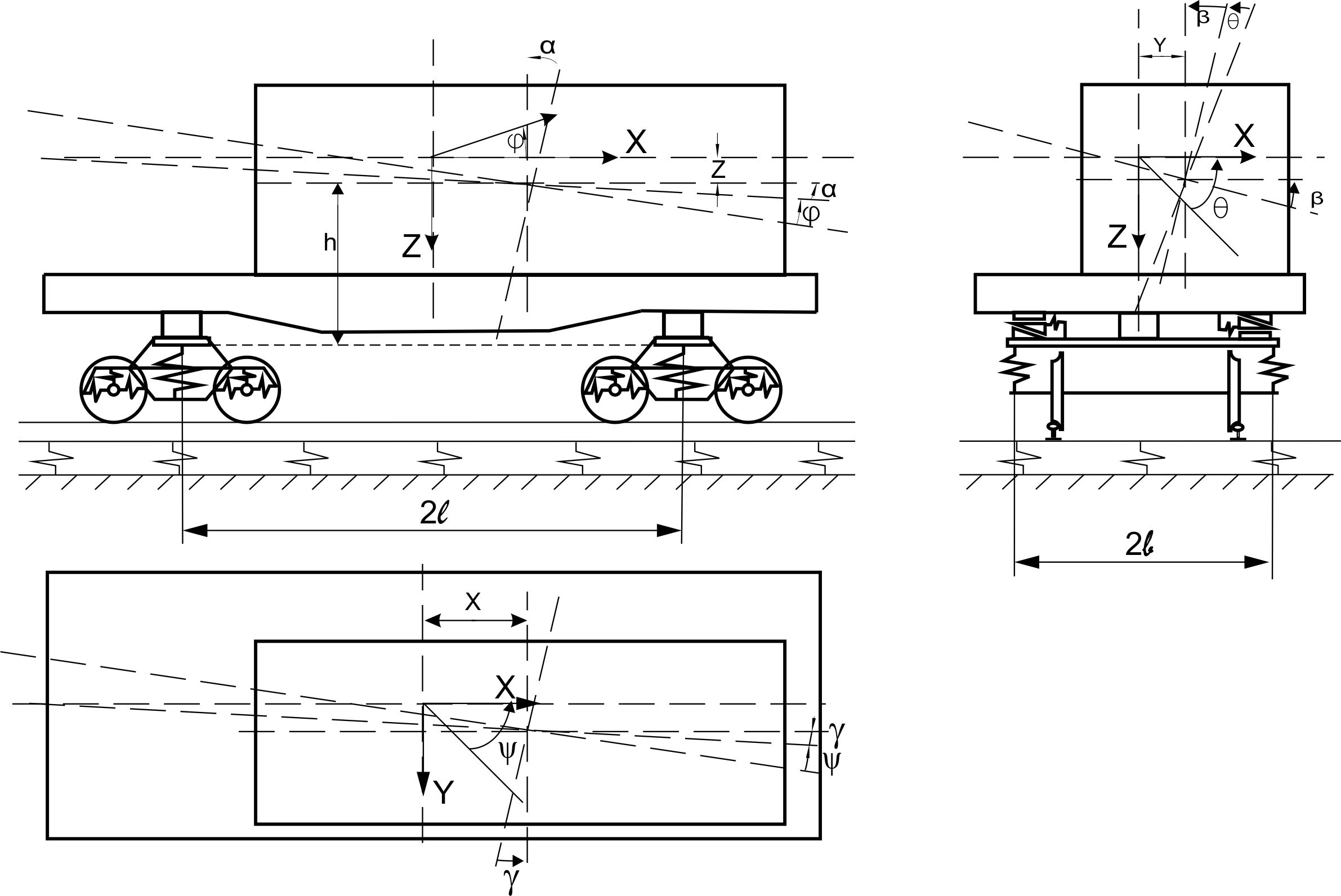
Fig. 3. Calculation
scheme of 4-axle flat wagon with asymmetric load arrangement
Standard and
technical requirements for positioning and fastening of goods in an
open rolling stock are presented in [7, 12]. In accordance with the
current requirements, the total center of gravity of goods ( )
should be located on the intersection of the longitudinal and
lateral plane of symmetry of the wagon. The shift of
relative to the longitudinal and lateral planes of the wagon
symmetry is allowed (Table 2), if there are objective reasons for
this (geometric parameters of the load, arrangement and fastening
conditions).
)
should be located on the intersection of the longitudinal and
lateral plane of symmetry of the wagon. The shift of
relative to the longitudinal and lateral planes of the wagon
symmetry is allowed (Table 2), if there are objective reasons for
this (geometric parameters of the load, arrangement and fastening
conditions).
Table 2
Permissible
longitudinal
shift
of
the
common
load
center
in
a
4-axle
wagon
|
Para-meter
|
Load
weight, t
|
|
<10
|
15
|
20
|
25
|
30
|
35
|
40
|
45
|
50
|
55
|
60
|
62
|
67
|
70
|
>70
|
|
lsh
cm
|
during
loading
|
|
270
|
225
|
195
|
155
|
125
|
110
|
95
|
85
|
75
|
68
|
60
|
55
|
20
|
0
|
0
|
|
along
the track
|
|
300
|
248
|
216
|
173
|
144
|
123,5
|
108
|
96
|
86,5
|
78,5
|
72
|
63
|
26
|
6
|
0
|
The
permissible value of
shift
in the longitudinal direction lsh
(relative to the lateral plane of symmetry) during loading and along
the track is determined in accordance with Table 2 depending on the
total weight of the load in the wagon.
According to [7, 12], in the
case of necessity of asymmetric arrangement of load in a wagon, the
difference in loading of bogies should not exceed for 4-axle wagons
– 10 t, and the loading, which falls on each of the bogies, should
not exceed half of the carrying capacity of the wagon.
The
permissible value of
shift in the lateral direction bsh
(relative to the longitudinal plane of symmetry) during loading and
along the track is determined in accordance with Table 3 depending
on the total weight of the load in the wagon and the height of the
common gravity centre of the wagon with load ( )
above the level of the top of rail TOR [7, 12].
)
above the level of the top of rail TOR [7, 12].
Table
3
Permissible
lateral shift of the common load center in a 4-axle wagon
|
Parameter
|
Load
weight, t
|
|
≤10
|
30
|
50
|
55
|
67
|
>67
|
|
Height
of common gravity center of wagon with load over the TOR, m
|
|
≤1,2
|
1,5
|
2,0
|
≤1,2
|
1,5
|
2,0
|
2,3
|
≤1,2
|
1,5
|
2,0
|
2,3
|
≤1,5
|
2,0
|
2,3
|
≤1,5
|
2,0
|
2,3
|
≤2,3
|
|
bsh,
cm
|
during
loading
|
|
45
|
38
|
29
|
38
|
31
|
25
|
20
|
25
|
20
|
18
|
14
|
15
|
12
|
10
|
12,5
|
9,5
|
8,0
|
7,0
|
|
along
the track
|
|
62
|
55
|
41
|
55
|
45
|
35
|
28
|
35
|
28
|
25
|
20
|
22
|
17
|
15
|
18
|
14
|
12
|
10
|
Simultaneous
shift of
relative to the longitudinal and lateral
symmetry of the wagon (Fig. 4) is allowed within the limits given in
Tables 2, 3.
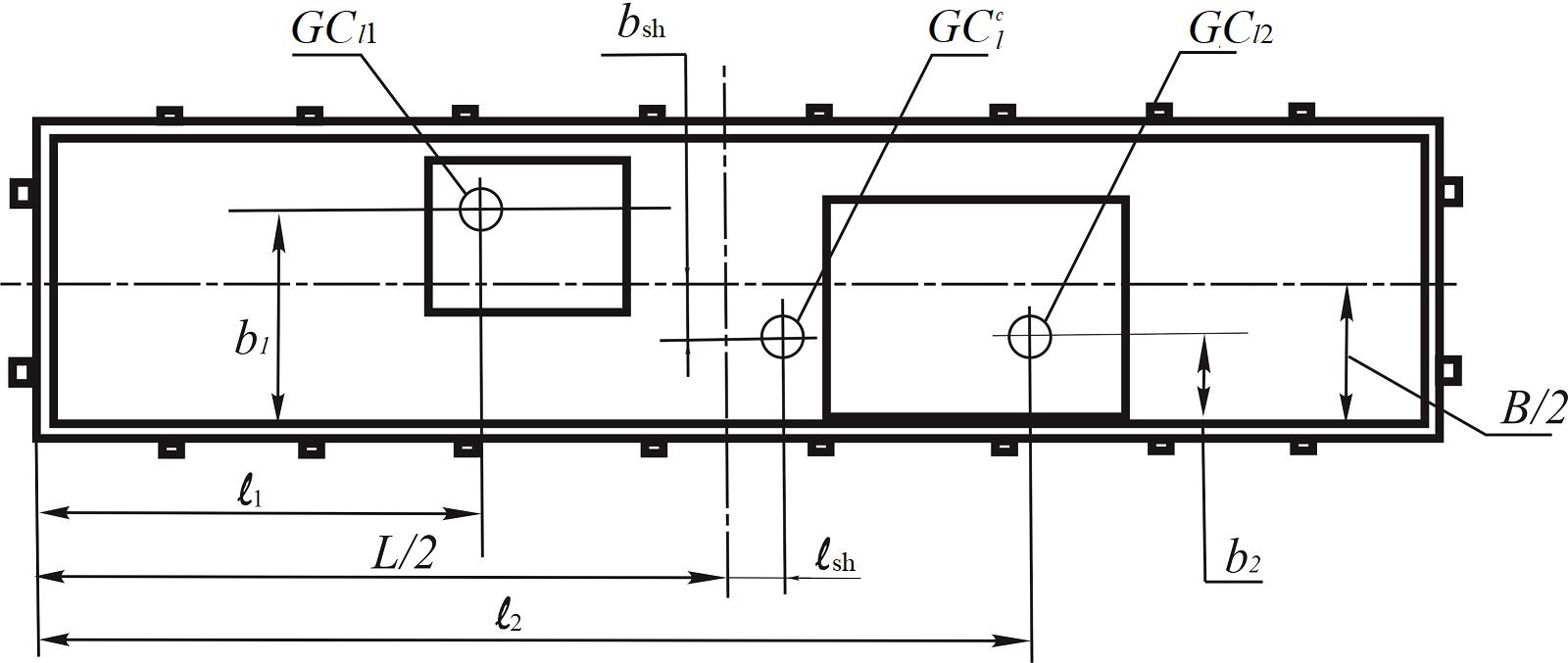
Fig.
4. Calculation scheme for determining the longitudinal and lateral
shift
of the common load centre in a wagon
It is allowed to transport two
loads (or groups of loads) of the same weight with their
skew-symmetric arrangement in the wagon (Fig. 5), subject to the
following conditions:
– the
height of
the common
gravity center
of the
wagon with
load ()
above TOR
does not
exceed 230 cm;
– the
distances
between the
load gravity
centers
 and
and
 in the longitudinal and lateral directions
do not exceed the allowable values taking into account the total
load weight in accordance with the Table 4;
in the longitudinal and lateral directions
do not exceed the allowable values taking into account the total
load weight in accordance with the Table 4;
–
is located at the intersection of the
longitudinal and lateral plane of the wagon symmetry.
The total weight of the load and
means of its fastening in the wagon shall not exceed its maximum
load capacity, and in the case of loading supported by two wagons,
the proportion of the weight of the load and the means of its
fastening, which falls on each loaded coupled wagon, shall not
exceed the maximum load capacity of the wagon. The load overrun in
its longitudinal direction beyond the limits of the headstock of the
flat wagon frame must not exceed 40 cm [7, 12].
Table 4
Maximum
allowable distances between load centers with skew-symmetric
arrangement in a wagon
|
Parameter
|
Total
weight of two loads, t
|
|
|
≤20
|
30
|
40
|
50
|
55
|
67
|
72
|
|
 ,
cm ,
cm
|
800
|
700
|
600
|
600
|
600
|
500
|
450
|
|
 ,
cm ,
cm
|
125
|
90
|
75
|
60
|
50
|
40
|
35
|
When the load
is placed on a flat wagon on two supports, laid across its frame
symmetrically relative to the lateral plane of symmetry of the flat
wagon, the location of the supports is determined depending on the
load on the support and the width
 of the load distribution on the flat wagon
frame. In the case of support placement within or outside the flat
wagon base (Fig. 6, a, b),
the minimum permissible distance
of the load distribution on the flat wagon
frame. In the case of support placement within or outside the flat
wagon base (Fig. 6, a, b),
the minimum permissible distance
 between the longitudinal axis of the
support and the lateral plane of the flat wagon symmetry is
determined in accordance with Table 5.
between the longitudinal axis of the
support and the lateral plane of the flat wagon symmetry is
determined in accordance with Table 5.
In case of
asymmetric location of gravity centre of the load or the support
relative to the lateral plane of the wagon symmetry, a checking
calculation of the bending moment of the wagon frame shall be
performed. It is also necessary to perform a checking calculation of
the bending moment of the flat wagon frame when arranging support at
a distance that does not meet the requirements of Table 5.
a
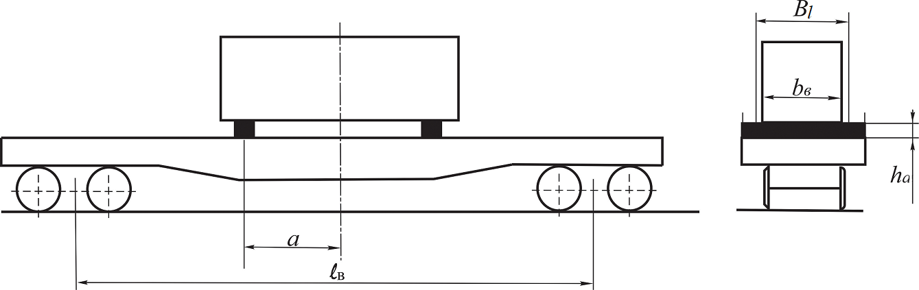
b
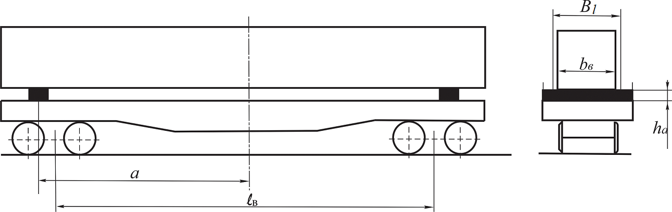
Fig.
6. Load arrangement on two supports located:
a
– within the flat wagon base; b
– outside the flat wagon base
Table
5
Maximum
permissible distances between the longitudinal axis of the support
and the lateral plane of the flat wagon symmetry
|
Location
of supports
within the
flat wagon
base
|
Location
of supports
outside the
flat wagon
base
|
|
Load
on one support, tc
|
Minimum
permissible distance
 (
cm) at width Bl
(cm) of load distribution (
cm) at width Bl
(cm) of load distribution
|
Load
on one support, tc
|
Minimum
permissible distance
(
cm) at width Bl
(cm) of load distribution
|
|
|
88
|
178
|
270
|
|
88
|
178
|
270
|
|
<20
|
55
|
32.5
|
0
|
<12.5
|
625
|
635
|
640
|
|
22
|
95
|
75
|
50
|
15.0
|
600
|
605
|
615
|
|
25
|
120
|
110
|
90
|
20.0
|
560
|
565
|
575
|
|
27
|
142.5
|
135
|
1,20
|
25.0
|
540
|
545
|
555
|
|
30
|
167.5
|
160
|
145
|
30.0
|
537
|
542
|
552
|
|
33
|
207.5
|
188.5
|
185
|
33.0
|
535
|
540
|
550
|
|
36
|
310
|
290
|
240
|
36.0
|
533
|
538
|
550
|
It is
generally known that the railway rolling stock ability rating is
essential for ensuring the safety of trains, and the quality of
rolling stock depends on its design, fabrication and acceptance. At
each of these stages, the normative base plays a decisive role.
Levels of estimation and allowable values of ability rating in
accordance with normative documentation are given in Table 6 [6].
Table 6
Levels of
estimation and allowable values of ability rating
|
Indicator
|
Levels
of estimation
|
Allowable
values
|
|
empty
|
loaded
|
|
Maximum
coefficient
of dynamic
supplement
of the
spring-suspended
parts
(coefficient
of vertical
dynamics of
the central
suspension
stage)

|
excellent
|
0.5
|
0.2
|
|
good
|
0.6
|
0.35
|
|
satisfactorily
|
0.7
|
0.4
|
|
acceptable
|
0.75
|
0.65
|
|
Maximum
coefficient
of dynamic
supplement
of unsprung
parts
(coefficient
of vertical
dynamics of
the box
suspension
stage)
|
excellent
|
0.6
|
0.5
|
|
good
|
0.75
|
0.7
|
|
satisfactorily
|
0.85
|
0.8
|
|
acceptable
|
0.98
|
0.9
|
|
Maximum
ratio of
frame force
to static
axial load
(coefficient
of
horizontal
dynamics)

|
excellent
|
0.25
|
0.2
|
|
good
|
0.3
|
0.25
|
|
satisfactorily
|
0.38
|
0.3
|
|
acceptable
|
0.4
|
0.38
|
|
Wheel
derailment
safety
factor

|
acceptable
|
1.3
|
The Order of the Ministry of
Transport and Communications of Ukraine of May 18, 2010, No. 299 «On
Approval of the Procedure for the Development of Technical
Documentation on the Load Positioning and Fastening in Wagons and
Containers Transported by Rail» establishes requirements for
registration, approval and review of technical documentation for
transportation of loads in wa-gons and containers by railway
transport, control over the correct load positioning.
In accordance with the order for
the development and adjustment of technical documentation for the
carriage of goods by the manner not provided for by regulatory acts,
there must be the following information as well: determination of
inertial forces and wind force acting on the load; determination of
the stability of the wagon with load and load in the wagon; load on
the wagon bogies. The method of calculating the stability of the
wagon with load and load in the wagon contains the determination of
additional vertical load on the wheel from the action of centrifugal
forces and wind force, but does not take into account the dynamic
processes that arise during the movement of wagons on the railway
track in the presence of vertical and horizontal irregularities.
Maximum
coefficients of the dynamic supplement of the spring-suspended
and unsprung parts,
the maximum ratio of frame force to static axial load
and
the wheel derailment safety
factor
are
used to study the dynamic forces acting on the wagon bogie or body
components.
Findings
Theoretical
studies using the software complex developed by the BRL RSDS are
conducted under the condition of the movement of the flat wagon of
model 13–401 on typical bogies 18–100 at speeds ranging from 50
to 90 km/h in curves with radii of 350 and 600 m, with 130 and 120
mm canting,
respectively. Rails – P65, sleepers – wooden, ballast – broken
stone.
Wooden
sleepers to this day are the main type of rail support and it is
expedient to lay them:
– on
the ribbon
track in
horseshoe curves
with the
purpose of
expansion of
the rail
track to
prevent the
possible
derailment of
wagons;
– on
highly loaded
lines, where
the use
of continuous
welded track
with reinforced
concrete
sleepers is
ineffective.
In addition, wooden sleepers in
comparison with reinforced concrete ones have less rigidity and
resilience for the perception and even distribution of loads from
the rolling stock wheel sets on the rails, are less resistant to
deformation. The trains move smoother on rails with reinforced
concrete sleepers, since there are practically no joints at the
rails, thanks to the high stability in terms of transverse rows.
Therefore, when conducting calculations, wooden sleepers were chosen
as the basis of rail support [2].
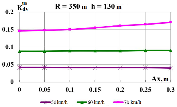
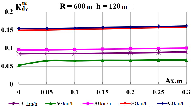
In the given
study we considered the influence of the load center shift on the
flat wagon in the longitudinal and transverse directions, as well as
in both directions simultaneously. Graphs of variance of the dynamic
parameters during the travel on curved tracks
 and 350 m are shown in Fig. 7-9. The shift
in the longitudinal direction (Fig. 7) is studied within the limits
and 350 m are shown in Fig. 7-9. The shift
in the longitudinal direction (Fig. 7) is studied within the limits
 ,
that is permitted
by the standards
(Table 2) [7, 12].
,
that is permitted
by the standards
(Table 2) [7, 12].
As can be
seen from Fig. 7, with the increased longitudinal shift of the load
center, the studied dynamic coefficients as a whole remain
unchanged. In the whole range of velocities, the indices
(Fig. 7 (a,
b)),
(Fig. 7 (c,
d)),
(Fig. 7 (e,
f)), and
(Fig. 7 (g,
h)), in case of increasing the
longitudinal shift from 0 to 0.3 m, do not exceed the permissible
norm both in the curve
m and in the curve
 m. The level of assessment is «excellent»
[6].
m. The level of assessment is «excellent»
[6].
From the results obtained, it
follows that the longitudinal shift of the load in case of increased
speed does not cause an increase in the dynamics, and their values
do not exceed the values determined by the current regulatory
documents [5].
The lateral
shift of the load is considered in the range from
 up to 0,2 m with a longitudinal shift
 m (Fig. 8). For loads weighing 50
t
with
m (Fig. 8). For loads weighing 50
t
with
 m, taken for calculations,
longitudinal shift of
m, taken for calculations,
longitudinal shift of
 m is allowed,
this value can be 0.2 m on the travel line
(Table 3, 4) [7, 12].
m is allowed,
this value can be 0.2 m on the travel line
(Table 3, 4) [7, 12].
a
b
c
d
e
f
g
h
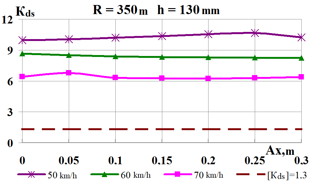
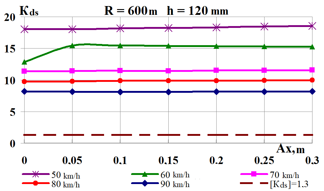
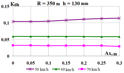
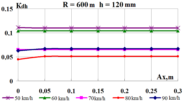
Fig.
7. Graphs of dependence on the load shift in the longitudinal
direction
while moving along the corresponding curve:
а,
b
–
coefficients
of the dynamic supplement of the spring-suspended parts;
c,
d
–
coefficients
of the dynamic supplement of unsprung parts;
e,
f
–
ratio
of the frame force to the static axial load;
g,
h
–
wheel
derailment safety factors
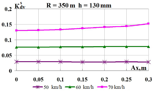
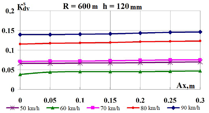
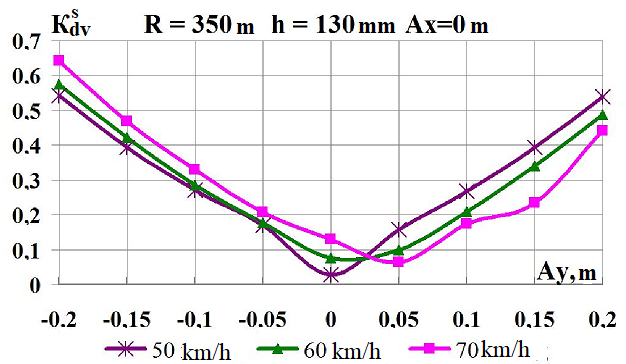
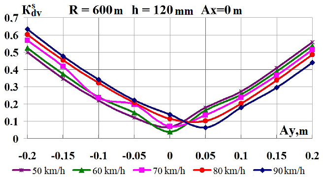
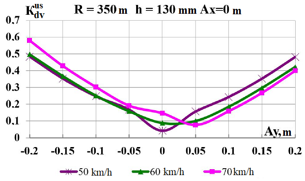
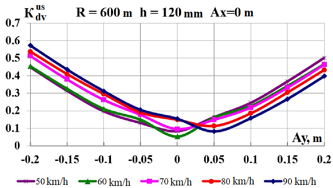
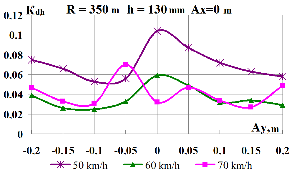
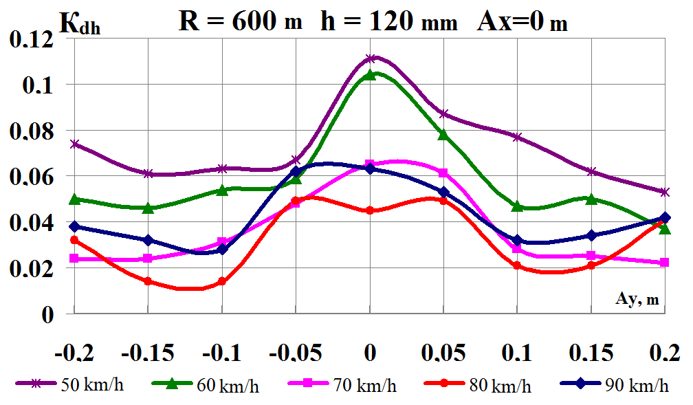
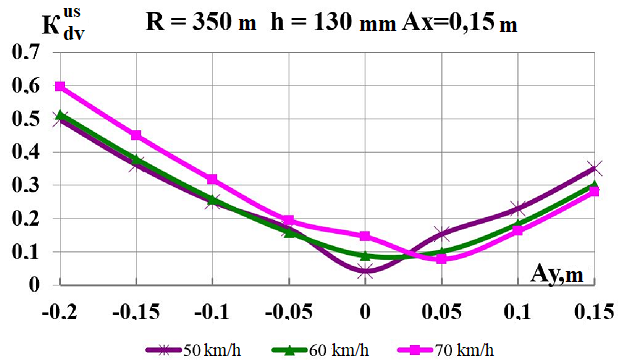
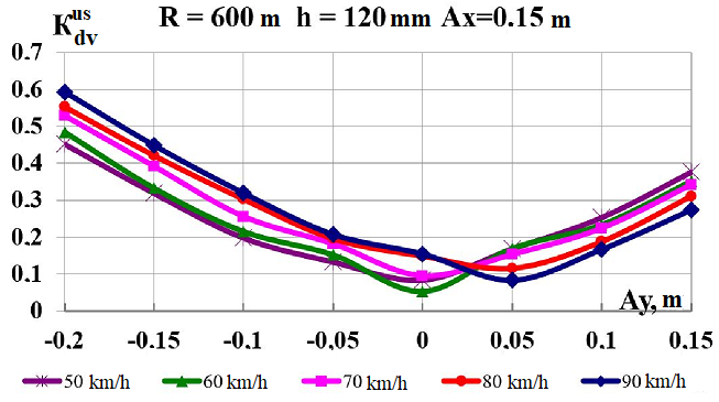
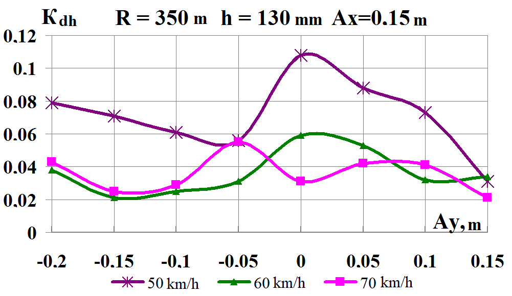
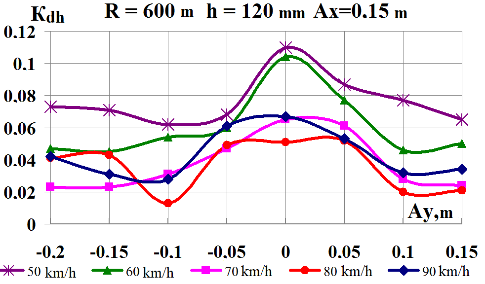
The
Figure 8 shows
the effect
on the
dynamic
indicators of
the lateral
load center
shift in
curves
m and
m, respectively.
The effect of lateral load center shift
has a more significant effect on the dynamic indicators than the
longitudinal shift. With the increase of
in both sides from the central lateral
axis, the coefficients of the dynamic supplement of the
spring-suspended
and
unsprung parts increase (Fig. 8, a–d),
the ratio of the frame force to the static axial load varies
considerably (Fig. 8, e, f).
With the growth oftowards
the wheel based on the inner rail, the dynamic figures even
decrease. The wheel derailment safety factors on the contrary are
significantly reduced (Fig. 8, g, h).
The level of
assessment from the lateral load center shift of the coefficients of
the dynamic supplement of the spring-suspended partsis
«acceptable», the coefficients of the dynamic supplement of the
unsprung parts
are «good», and the ratio of the frame force to the static axial
load
is «excellent» [5].
At
speed of
70-90 km/h,
in case
of increasing
lateral shift
from 0 to
the value
of 0.2 m
acceptable for
the indicated
weight, the
wheel derailment safety factor
is significantly
reduced in
both curves.
On the
curve
m (Fig.
8, g) the
values
for
m reach
a dangerous
value,
especially
taking into
account the
fact that
the given
results are
obtained when
the flat
wagon moves
along a
curve without
irregularities.
Therefore, exceeding the lateral shift
beyond the regulatory value of 0.15 m is inappropriate from the
point of view of traffic safety.
Consequently, the lateral load
center shift limitation, as defined by the regulatory documents,
must be observed, it is due to a sharp decrease in the wheel
derailment safety factor.
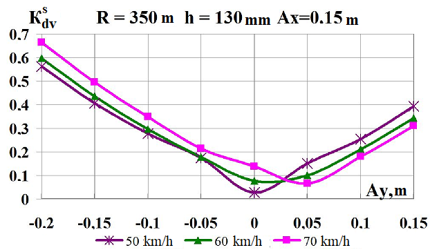
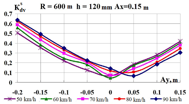
The
simultaneous
shift of
the gravity
center along
the axes
 is considered
within
and
from 0 and
0.15 m (Fig.
9) [7, 12].
is considered
within
and
from 0 and
0.15 m (Fig.
9) [7, 12].
Fig.
9 shows the
graphs of
the dependence
of the
dynamic
indicators on
the value
of the
load centre
shift in
the lateral
direction
for the
value of
the longitudinal
shift
 m. As
can be
seen from
the comparison
of the
graphs given
in Fig.
8 for
and Fig.
9 for за
m, differences
in indicators
,
and
are small, that
is, the
presence of
simultaneous
lateral and
longitudinal
load center shifts
practically does
not affect
the dynamic
indicators.
m. As
can be
seen from
the comparison
of the
graphs given
in Fig.
8 for
and Fig.
9 for за
m, differences
in indicators
,
and
are small, that
is, the
presence of
simultaneous
lateral and
longitudinal
load center shifts
practically does
not affect
the dynamic
indicators.
The
level of
assessment of
the coefficients
of the
dynamic
supplement of
the
spring-suspended
parts
is «acceptable»,
the coefficients
of the
dynamic
supplement of
the unsprung
parts
is «good»,
and the
ratio of
the frame
force to
the static
axial load
is «excellent»
for the
simultaneous
longitudinal and
lateral load
center shift. But
this shift
leads to
a significant
decrease in
the factor
.
As the
lateral load
center shift
of the
flat wagon
increases
towards the
wheel based on
the inner
rail, the
indices of
vary
considerably, as
can be
seen from
Fig. 9, (g,
h).
Therefore, the
limitation of
simultaneous
longitudinal and
lateral shift,
as defined
by the
regulatory
documents, must
be also
observed.
In addition, the calculations showed the impossibility of increasing
the travel speed in small radius curves due to the high probability
of the rolling stock derailment.
Originality
and practical value
This study includes the
development of me-thods of mathematical simulation of dynamic
processes of rolling stock and track interaction. Similar
theoretical calculations can be applied in the course of
quantitative and qualitative assessment of the impact of the load
center shift on the rolling stock ability rating, taking into
account the wear of parts and bogies while moving on the straight
and curved track with irregularities.
During the
study, the following scientific and practical results were obtained:
– mathematical
simulation of
five coupled
wagons for
studying the
dynamic loading
of a
flat wagon
with heavy
load;
– assessment
of the
basic dynamic
indicators at
a shift
of the
gravity center
of heavy
load during
movement on
curved railway
track;
– substantiation
and introduction
of the
maximum possible
values of
lateral shift
of the
heavy load
gravity center
during
transportation
on flat
wagons.
a
b
e
f
c
d
g
h
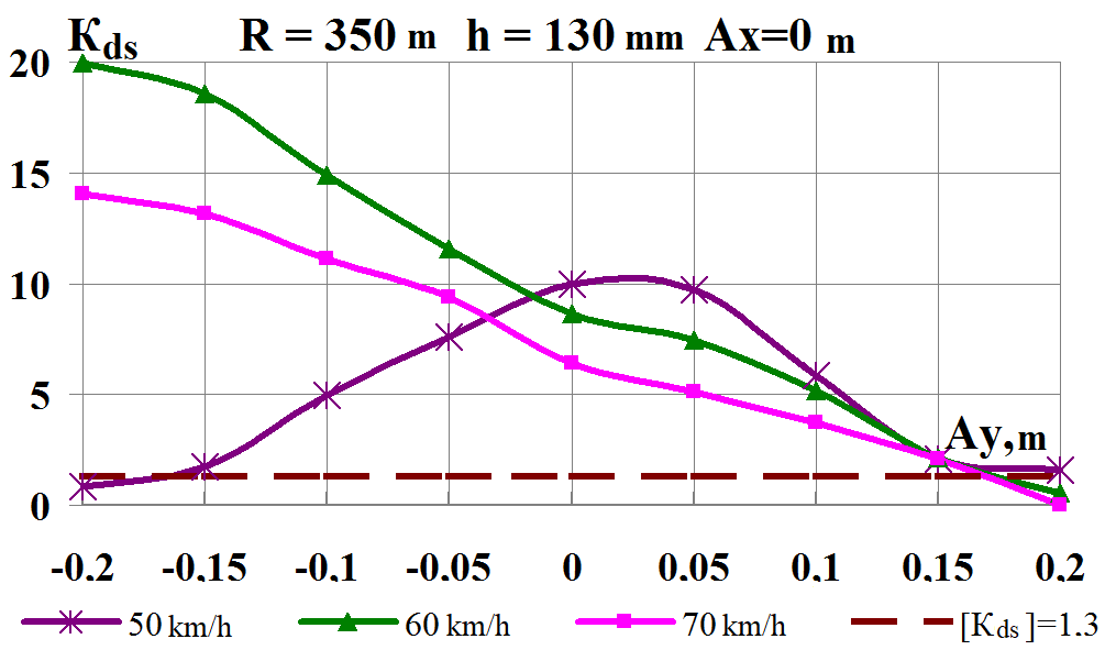
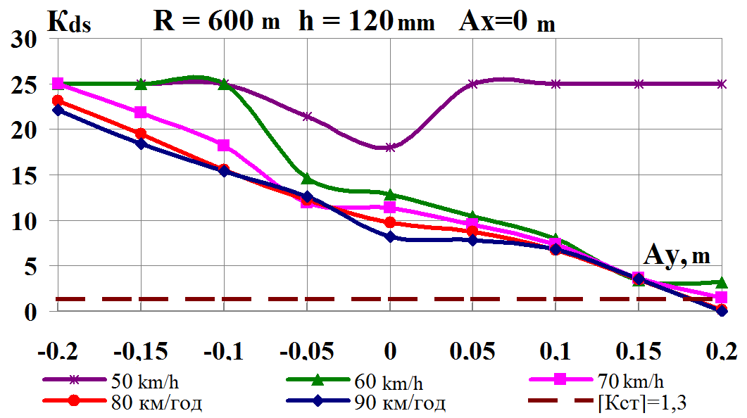
Fig. 8. Graphs of
dependence on the load shift in the lateral direction while moving
along the corresponding curve:
а,
b
–
coefficients of
the dynamic supplement of the spring-suspended parts;
c,
d
–
coefficients of
the dynamic supplement of unsprung parts;
e,
f
–
ratio of the frame
force to the static axial load;
g,
h
–
wheel derailment
safety factors
a
b
c
d
e
f
g
h
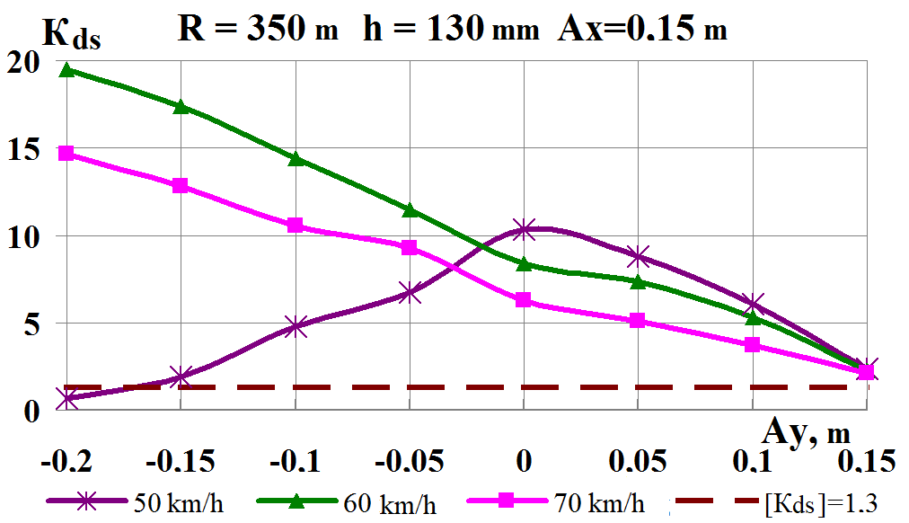
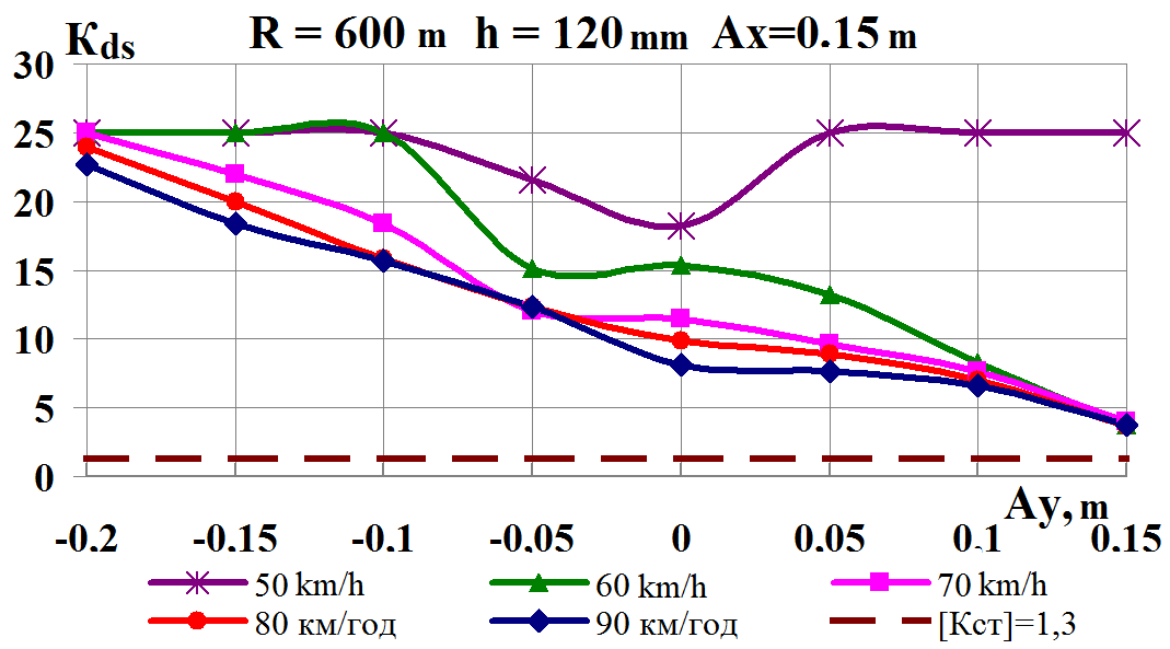
Fig.
9. Graphs of dependence on simultaneous load shift in the lateral
and longitudinal
directions while moving along the corresponding
curve:
а,
b
–
coefficients
of the dynamic supplement of the spring-suspended parts;
c,
d
– coefficients of the dynamic supplement of unsprung parts;
e,
f
– ratio of the frame force to the static axial load; g,
h
– wheel derailment safety factors
Conclusions
Based
on the
analysis of
the conducted
theoretical
studies of
the rolling
stock dynamic
qualities on
example of
the flat
wagon, it
is possible
to draw
the following
conclusions:
– Longitudinal
shifts of
the load
weighing 63 tons
do not
result in
increasing of
the coefficients
of the
dynamic
supplement of
the
spring-suspended
and unsprung
parts, the
ratio of
the frame
force to
the static
axle load,
as well
as the
wheel derailment
safety factor;
– Longitudinal
shifts of
the load
center have
a significantly
less influence
on the
dynamic forces
that arise
when the
flat wagon
moves than
the lateral
shift, or
the presence
of simultaneous
shift in
both directions
from the
axis of
symmetry;
– Limitation
of the lateral shift set by the regulatory documents must be
observed; it is caused not by an increase in the dynamics
coefficients, but by a sharp decrease in the wheel derailment safety
factor;
– Exceeding
the lateral
shift of
the load
center on
the flat
wagon frame
beyond the
regulatory value
of 0.15 m
is inappropriate
from the
point of
view of
traffic safety.
LIST OF REFERENCE LINKS
Бабаев, А.
М. Динамико-прочностные качества сцепа
платформ с упругим грузом / А. М. Бабаев,
В. А. Каблуков, А. В. Шатунов // Динамика
вагонов : сб. науч. тр. /
Петербург. ин-т инж. ж.-д. трансп. –
Санкт-Петербург, 1993. – С. 118–120.
Даніленко,
Е. І. Залізнична колія : підручник для
вищ. навч. закл. : у 2 т. / Е. І. Даніленко.
– Київ : Інпрес, 2010. – Т. 1. – 528 с.
Данович, В.
Д. Колебания в горизонтальной плоскости
4-осн. платформы с несимметрично
расположенным тяжеловесным грузом /
В. Д. Данович, П. С. Анисимов // Вестн.
ВНИИЖТ. – 1989. – № 3. – С. 5–9.
Данович, В.
Д. Математическая модель пространственных
колебаний сцепа пяти вагонов, движущихся
по прямолинейному участку пути / В. Д.
Данович, А. А. Малышева // Транспорт.
Нагруженность и прочность подвижного
состава : сб. науч. тр.
/ Днепропетр. гос. техн.
ун-т ж.-д. трансп. – Днепропетровск,
1998. – С. 62–69.
Данович, В.
Д. Пространственные колебания вагонов
на инерционном основании : дис. д-ра
техн. наук / Данович Виктор Данилович
;
Днепропетр. ин-т инж. ж.-д. трансп.
– Днепропетровск, 1981.
– 465 с.
ДСТУ
ГОСТ 33211:2017. Вагони вантажні. Вимоги до
міцності та динамічних якостей
(ГОСТ
33211-2014, IDТ). – Введ.
2017–07–01. – Київ : УкрНДНЦ, 2017. – 58 с.
Збірник
№ 17 Правил
перевезення і тарифів залізничного
транспорту України. – Київ : САМ, 2005. –
176 с.
Определение
допустимых сил при оценке устойчивости
грузовых вагонов от выжимания в поездах
/ А. А. Швец, К. И. Железнов, А. С. Акулов,
А. Н. Заболотный, Е. В. Чабанюк // Наука
та прогрес транспорту. – 2016. – № 1 (61).
– С. 189–192. doi: 10.15802/stp2016/61045
Определение
показателей безопасности движения
платформ с порожним автопоездом / А.
В. Шатунов, В. В. Соборницкая, Е. Н. Ковтун,
О. М. Маркова // Транспорт : сб.
науч. тр. / Днепропетр.
гос. техн. ун-т ж.-д. трансп. –
Днепропетровск, 2001. – Вып. 7. – С. 116–120.
Підвищення
ефективності оперативного керування
локомотивним парком залізниць України
: монографія / Д. М. Козаченко, Р. В.
Вернигора, Л. О. Єльнікова, М. І. Березовий
; Дніпропетр. нац. ун-т залізн. трансп.
ім. акад. В. Лазаряна. – Дніпро : Герда,
2017. – 164 с.
Теоретическая
оценка динамических качеств платформ,
загруженных автопоездом с грузом / А.
В. Шатунов, В. В. Соборницкая, Е. Н. Ковтун,
О. М. Маркова // Транспорт : сб.
науч. тр. / Днепропетр.
гос. техн. ун-т ж.-д. трансп. –
Днепропетровск, 2000. – Вып. 3. – С. 21–27.
Технические
условия размещения и крепления грузов.
Приложение 3 к Соглашению о
международном железнодорожном грузовом
сообщении (СМГС). – Київ
: Девольта, 2011.
– Т. 1. – 436
с.
Шатунов, А.
В. Нагруженность
сцепа из двух платформ при ресурсосберегающем
способе транспортировки длинномерных
грузов : автореф. дис.
канд. техн. наук : 05.22.07 /
Шатунов Александр Васильевич ;
Днепропетр. ин-т инж. ж.-д. трансп. –
Днепропетровск, 1992.
– 17 с.
Швець,
А. О. Вплив поздовжнього та поперечного
зміщення центру ваги вантажу в піввагонах
на їх динамічні показники / А. О. Швець
// Наука та прогрес
транспорту. – 2018. – № 5
(77). – С. 115–128.
doi: 10.15802/stp2018/146432
Determination
of the issue concerning the lift resistance factor of lightweight
car / A. O.
Shvets, К. I. Zhelieznov, А.
S. Аkulov, О.
M. Zabolotnyi, Y. V. Chabaniuk // Наука
та прогрес транспорту. –
2015. –
№
6 (60). – С. 134–148. doi:
10.15802/stp2015/57098
Effect
of the state of car running gears and railway track on wheel and
rail wear / E. P. Blokhin,
O. M. Pshinko, V. D. Danovich, M. L.
Korotenko // Railway Bogies and Running Gears : Proc. of the 4th
Intern. Conf. / Technical University of Budapest. – Budapest,
1998. – P. 313–323.
McKinnon,
A. C.
Freight Transport Deceleration: Its
Possible Contribution to the Decarbonisation of Logistics
/ A.
C. McKinnon // Transport
Reviews. – 2016.
– Vol. 36.
– Iss. 4.
– P. 418–436.
doi:
10.1080/01441647.2015.1137992
Modeling,
simulation and applications of
longitudinal train dynamics / C.
Cole, M.
Spiryagin, Q.
Wu,
Y.
Q. Sun //
Vehicle System Dynamics.
– 2017. –
Vol. 55. – Іss.
10. – P.
1498–1571.
doi: 10.1080/00423114.2017.1330484
Navarrete,
J. A. Experimental and theoretical modeling of cargo sloshing
during braking / J. A. Navarrete,
F. Otremba // ASME
International Mechanical Engineering Congress and Exposition
(Phoenix,
Arizona, USA, Nov.
11–17, 2016). –
Phoenix, 2016.
– Vol. 4B :
Dynamics, Vibration, and Control.
doi: 10.1115/imece2016-65698
Ramos,
A. G. A new load balance methodology for container loading problem
in road transportation /
A. G. Ramos, E. Silva, J. F. Oliveira
// European Journal of Operational Research. – 2018. – Vol.
266. – Іss.
3. – P. 1140–1152. doi:
10.1016/j.ejor.2017.10.050
Wu,
H. Effects of
wheel and rail profiles on vehicle performance
/ H.
Wu // Vehicle
System Dynamics. – 2006.
– Vol. 44. –
Іss.
sup1. – P.
541–550.
doi: 10.1080/00423110600875393
Wu,
Q. Longitudinal
train dynamics: an
overview / Q.
Wu, M. Spiryagin,
C. Cole //
Vehicle System Dynamics.
– 2016. –
Vol. 54. –
Іss. 12.
– P. 1688–1714.
doi: 10.1080/00423114.2016.1228988
О.
В. Шатунов1*,
А. О. Швець2*
1*Каф.
«Вагони та вагонне господарство»,
Дніпровський національний університет
залізничного
транспорту імені академіка
В. Лазаряна, вул. Лазаряна, 2, Дніпро,
Україна, 49010, тел.
+38 (067) 953 60
14,
ел. пошта
shatunov220648@gmail.com,
ORCID 0000-0002-1115-0093
2*Каф.
«Теоретична та будівельна механіка»,
Дніпровський національний університет
залізничного
транспорту імені академіка
В. Лазаряна, вул. Лазаряна, 2, Дніпро,
Україна, 49010, тел.
+38 (050) 214 14 19,
ел. пошта angela_Shvets@ua.fm, ORCID
0000-0002-8469-3902
дослідження
динамічних ПОКАЗНИКів Платформи
В РАЗІ
зміщення центра Тяжіння вантажу
Мета.
Визначення впливу поздовжнього й
поперечного зміщення центра тяжіння
великовагового вантажу на платформах,
з урахуванням швидкості руху, на основні
динамічні показники – максимальні
коефіцієнти динамічної добавки
обресорених і необресорених частин,
максимальне відношення рамної сили до
статичного осьового навантаження,
коефіцієнт стійкості колеса від
сходження з рейок. Методика.
За основу дослідження взято метод
математичного та комп’ютерного
моделювання динамічної навантаженості
платформи з використанням моделі
просторових коливань зчепу з п’яти
вагонів і програмного комплексу,
розробленого в галузевій науково-дослідній
лабораторії динаміки й міцності рухомого
складу (ГНДЛ ДМРС). Теоретичні дослідження
проведені за умови руху платформи
моделі 13–401 з типовими візками 18–100 зі
швидкостями в інтервалі від 50 до 90
км/год по кривих із радіусами 350 й 600 м,
із підвищеннями зовнішньої рейки 130 і
120 мм відповідно. Результати.
Подано аналіз теоретичних
досліджень динамічних якостей рухомого
складу на прикладі платформ. Розрахунки
проведені з використанням пакета
прикладних програм. У ході виконання
теоретичних досліджень і після проведення
моделювання з урахуванням процесів
коливання вагона-платформи й вантажу,
за наявності поздовжнього й поперечного
зміщення його центра тяжіння, отримано
залежності основних динамічних
показників з огляду на величину швидкості
руху. Наукова новизна.
Для визначення динамічної навантаженості
вагона платформи, із застосуванням
математичної моделі зчепу з п’яти
вантажних вагонів, досліджено вплив
зміщення у двох напрямках від центральної
осі симетрії центра тяжіння великовагового
вантажу з огляду на величину швидкості
руху по кривих ділянках колії малого
й середнього радіуса.
Практична значимість.
У результаті проведених теоретичних
досліджень обґрунтовано рекомендації
стосовно максимально можливих величин
зміщення центра тяжіння великовагових
вантажів під час їх транспортування
на вагонах-платформах.
Ключові
слова: вантаж; вагон-платформа;
динамічні показники; криві ділянки
колії; поздовжнє й поперечне зміщення;
центр тяжіння; швидкість руху
А.
В. Шатунов1*,
А. А. Швец2*
1*Каф.
«Вагоны и вагонное хозяйство», Днипровский
национальный университет железнодорожного
транспорта имени академика В. Лазаряна,
ул. Лазаряна, 2, Днипро, Украина, 49010, тел.
+38 (067) 953 60 14,
эл. почта shatunov220648@gmail.com,
ORCID 0000-0002-1115-0093
2*Каф.
«Теоретическая и строительная механика»,
Днипровский национальный университет
железнодорожного
транспорта имени
академика В. Лазаряна, ул. Лазаряна, 2,
Днипро, Украина, 49010, тел. +38 (050) 214 14 19,
эл. почта angela_Shvets@ua.fm, ORCID 0000-0002-8469-3902
исследование
ДИНАМИЧЕСКИх ПОКАЗАТЕЛей
платформы
при смещении центра тяжести груза
Цель.
Определение влияния продольного и
поперечного смещения центра тяжести
тяжеловесного груза на платформах, с
учетом скорости движения на основные
динамические показатели – максимальные
коэффициенты динамической добавки
обрессоренных и необрессоренных частей,
максимальное отношения рамной силы к
статической осевой нагрузке, коэффициент
устойчивости колеса от схода с рельсов.
Методика.
Основой исследования является метод
математического и компьютерного
моделирования динамической нагруженности
платформы с использованием модели
пространственных колебаний сцепа из
пяти вагонов и программного комплекса,
разработанного в отраслевой
научно-исследовательской лаборатории
динамики и прочности подвижного состава
(ОНИЛ ДППС). Теоретические исследования
проведены при движении платформы модели
13–401 с типичными тележками 18–100 со
скоростями в интервале от 50 до 90 км/ч
по кривым с радиусами 350 и 600 м, с
возвышением наружного рельса 130 и 120 мм
соответственно. Результаты.
Представлен анализ теоретических
исследований динамических качеств
подвижного состава на примере платформ.
Расчеты проведены с использованием
пакета прикладных программ. В ходе
выполнения теоретических исследований
и после моделирования с учетом процессов
колебания вагона-платформы и груза,
при наличии продольного и поперечного
смещения его центра тяжести, получены
зависимости основных динамических
показателей на основании величины
скорости движения. Научная
новизна. Для определения
динамической нагруженности
вагона-платформы, с применением
математической модели сцепа из пяти
грузовых вагонов, исследовано влияние
смещения в двух направлениях от
центральной оси симметрии центра
тяжести тяжеловесного груза с учетом
величины скорости движения по
криволинейным участкам пути малого и
среднего радиуса. Практическая
значимость. В результате
проведенных теоретических исследований
обоснованы рекомендации относительно
максимально возможных величин смещения
центра тяжести тяжеловесных грузов
при их транспортировке на вагонах-платформах.
Ключевые
слова: груз; вагон-платформа;
динамические показатели; кривые участки
пути; продольное и поперечное смещение;
центр тяжести; скорость движения
REFERENCES
Babaev,
A. M.,
Kablukov, V.
A., &
Shatunov, A.
V. (1993).
Dinamiko-prochnostnye kachestva scepa platform s uprugim gruzom.
Dynamics of cars
(рр. 118-120).
St. Petersburg. (in Russian)
Danilenko,
E. I. (2010). Zaliznychna
koliia:
pidruchnyk
dlia
vyshchykh
navchalnykh
zakladiv.
(Vol. 1-2). Kyiv: Inpres. (in
Ukrainian)
Danovich,
V. D., & Anisimov, P. S. (1989). Kolebaniya v gorizontalnoy
ploskosti 4-osn. platformy s nesimmetrichno raspolozhennym
tyazhelovesnym gruzom. Vestnik of the
Railway Research Institute, 3, 5-9.
(in Russian)
Danovich,
V. D., & Malysheva, A. A. (1998). Mathematical Model of Spatial
Oscillations of the Coupling of Five Cars Moving Along a
Rectilinear Section of the Track.
Transport. Stress loading and
durability of a rolling stock (рр.
62-69).
Dnepropetrovsk.
(in Russian)
Danovich,
V. D. (1981). Spatial Cars
Oscillations in Inertia Track.
(Dysertatsiia doktora tekhnichnykh nauk). Dnepropetrovsk Institute
of Railway Transport Engineering, Dnеpropetrovsk.
(in Russian)
Vahony
vantazhni. Vymohy do mitsnosti ta dynamichnykh yakostei, 58 DSTU
33211:2017 (2017). (in Ukrainian)
Zbirnyk
№ 17 Pravyl perevezennia i taryfiv zaliznychnoho transportu
Ukrainy. (2005). Kуiv: SAM. (in
Ukrainian)
Shvets,
A. A., Zheleznov, K. I., Akulov, A. S., Zabolotny, A. N., &
Chabanyuk, E. V. (2016). Determination the permissible forces in
assessing the lift resistant factor of freight cars in trains.
Science and Transport Progress, 1(61),
189-192. doi:
10.15802/stp2016/61045 (in Russian)
Shatunov,
A. V., Sobornitskaya, V. V., Kovtun, E. N., & Markova, O. M.
(2001). Opredelenie pokazatelej bezopasnosti dvizheniya platform s
porozhnim avtopoezdom. Transport,
7, 116-120. (in Russian)
Kozachenko,
D. M., Vernigora, R. V., Yelnikova, L. O., & Berezovy, M. I.
(2017). Pidvyshchennia efektyvnosti
operatyvnoho keruvannia lokomotyvnym parkom zaliznyts Ukrainy:
Monohrafiia.
Dnipro: Herda.
(in Ukrainian)
Shatunov,
A. V., Sobornitskaya, V. V., Kovtun, E. N., & Markova, O. M.
(2000). Teoreticheskaya ocenka dinamicheskih kachestv platform,
zagruzhennyh avtopoezdom s gruzom. Transport,
3, 21-27. (in Russian)
Tekhnicheskie
usloviya razmeshcheniya i krepleniya gruzov.
Prilozhenie 3 k Soglasheniyu o
mezhdunarodnom zheleznodorozhnom gruzovom soobshchenii (SMGS).
(2011). Kyiv:
Devolta. (in
Russian)
Shatunov,
A. V.
(1992). Nagruzhennost
stsepa
iz
dvukh
platform
pri
resursosberegayushchem
sposobe
transportirovki
dlinnomernykh
gruzov.
(Avtoreferat dysertatsii kandydata tekhnichnykh nauk).
Dnepropetrovsk Institute of
Railway Transport Engineering, Dnеpropetrovsk.
(in Russian)
Shvets,
A. O. (2018). Influence of the longitudinal and transverse
displacement of the center of gravity of the load in gondola cars
on their dynamic indicators. Science
and Transport Progress,
5(77),
115-128.
doi: 10.15802/stp2018/146432 (in
Ukrainian)
Shvets,
A. A., Zhelieznov, K. I., Akulov, A. S., Zabolotnyi, A. N., &
Chabaniuk, Y. V. (2015). Determination of the issue concerning the
lift resistance factor of lightweight car. Science
and Transport Progress,
6(60), 134-148.
doi: 10.15802/stp2015/57098 (in
English)
Blokhin,
E. P., Pshinko, O. M., Danovich, V. D., & Korotenko,
M. L. (1998). Effect of the state of car running gears and railway
track on wheel and rail wear. Railway
Bogies and Running Gears: Proceedings of the 4th International
Conference (рр.
313-323).
Budapest. (in English)
McKinnon,
A. C. (2016). Freight Transport Deceleration: Its Possible
Contribution to the Decarbonisation of Logistics. Transport
Reviews, 36(4), 418-436. doi:
10.1080/01441647.2015.1137992 (in
English)
Cole,
C., Spiryagin, M., Wu, Q., & Sun, Y. Q. (2017). Modeling,
simulation and applications of longitudinal train dynamics. Vehicle
System Dynamics, 55(10), 1498-1571.
doi: 10.1080/00423114.2017.1330484
(in English)
Navarrete,
J. A., & Otremba, F. (2016). Experimental and theoretical
modeling of cargo sloshing during braking. ASME International
Mechanical Engineering Congress and Exposition (Phoenix, Arizona,
USA, Nov. 11-17,
2016).
Dynamics, Vibration, and Control,
4B.
Phoenix. doi: 10.1115/IMECE201665698
(in English)
Ramos,
A. G., Silva, E., & Oliveira, J. F. (2018). A new load balance
methodology for container loading problem in road transportation.
European Journal of Operational
Research, 226(3),
1140-1152.
doi: 10.1016/j.ejor.2017.10.050 (in English)
Wu,
H. (2006). Effects of wheel and rail profiles on vehicle
performance. Vehicle System Dynamics,
44(sup1), 541-550. doi:
10.1080/00423110600875393 (in English)
Wu,
Q., Spiryagin, M., & Cole, C. (2016). Longitudinal train
dynamics: an overview. Vehicle System
Dynamics, 54(12), 1688-1714. doi:
10.1080/00423114.2016.1228988 (in
English)
Received: Nov. 23, 2018
Accepted:
March 27, 2019