ISSN
2307–3489 (Print), ІSSN 2307–6666 (Online)
Наука
та прогрес транспорту. Вісник
Дніпропетровського
національного університету залізничного
транспорту, 2019, № 1
(79)
МАшинобудування
машинобудування
UDC 621.86/87(075.8)
L. M.
BONDARENKO1,
O.
P. Posmityukha2*,
K. T.
Hlavatskyi3
1Dep.
«Applied Mechanics and Material Science», Dnipro National
University of Railway
Transport named after Academician V. Lazaryan,
Lazaryan St., 2, Dnipro, Ukraine, 49600,
tel. +38 (056) 373 15 18,
e-mail bondarenko-l-m2015@yandex.ua, ORCID
0000-0002-2212-3058
2*Dep.
«Applied Mechanics and Material Science», Dnipro National
University of Railway
Transport named after Academician V. Lazaryan,
Lazaryan St., 2, Dnipro, Ukraine, 49600,
tel. +38 (066) 150 95 00,
e-mail AleksandrP@3g.ua, ORCID 0000-0002-9701-3873
3
Dep. «Applied Mechanics and Material
Science», Dnipro National University of Railway
Transport named
after Academician V. Lazaryan, Lazaryan St., 2, Dnipro, Ukraine,
49600,
tel. +38 (095) 816 99 90, e-mail kazimir.glavatskij@gmail.com,ORCID 0000-0003-0921-9845
ANALYTICAL DETERMINATION OF THE REDUCED
rotational
RESISTANCE
COEFFICIENT OF
THE CONSTRUCTION MACHINE
slewing gear
Purpose. Designing new models of construction
machines is closely related to the development of slewing gear, and
that, in turn, has a drive whose power and dimensions depend on the
rotational resistance and the reduced friction coefficient in the
units. The absence of analytical dependencies for determining the
reduced coefficient of friction for the rotation of construction
machines, first, restricts the designer's ability to select
materials, and secondly, does not allow the adoption of optimal
design solutions. Therefore, the purpose of the article is to find
analytical solutions to determine the rotational resistance in the
slewing gear of construction machines, which allows projecting more
advanced gears and machines in general. Existing techniques are based
on empirical dependencies and experimental coefficients that reduce
the accuracy of calculations, increase the size and cost of work. It
is proposed to improve the accuracy and simplify the process of
determining the rotational resistance and the magnitude of the
reduced rotational resistance coefficient of the building tower
cranes. Methodology. The set objectives can be achieved by
means of analytical dependencies for determination of rolling
friction coefficients over linear and point contacts. This will
enables to find the more accurate value of the resistance
coefficient, and the constructor during the calculations to take
targeted measures to reduce it, using the mechanical constants of
materials of the units and their geometric parameters. The
calculation is based on Hertz contact deformation theory and the body
point plane motion theory. Findings. The obtained dependencies
will allow analytically to find the resistance of rolling resistance
of rollers in construction machines with fixed and rotating pillars,
with circular rotary devices, as well as in ball and roller slewing
rings. The calculated values of the rotational resistance
coefficients for some types of mechanisms give similar values with
those recommended, while for others they significantly differ and
require their refinement in reference values. Originality of
the work consists in the use of analytical dependences for
determining the reduced coefficient of the rotational resistance over
linear and point contacts using Hertz contact deformation theory and
Tabor partial analytic dependencies theory. Practical value.
The obtained dependencies will allow to design new types of slewing
gear units of the construction machines and to reveal the additional
rotational resistances.
Keywords: construction machine;
resistance; rotation; turn; slewing ring; rail; rolling friction
Introduction
There are the following types
of slewing gears (SG) of the construction machines:
a) with a fixed pillar
consisting of an upper support with a thrust and radial bearings;
b) with a rotating pillar:
consists of a pillar connected to the revolving portion of the
construction tower crane;
c) with a circular flat or
tapered rail consisting of a series of conical or cylindrical
rollers, which come in contact with two rails on the revolving and
non-revolving portions of the construction crane;
g) with a slewing ring:
consists of ball or roller single-row or multi-row structures
(full-slewing and part-slewing excavators, motor graders).
One of the main causes of
rotational resistance is rolling resistance [12, 13]. There are many
studies and suggestions for its definition, but all of them are
either inaccurate, like Reynolds's assertion that rolling resistance
is the result of sliding friction at the contact point, or require
an experimental determination of one or more coefficients.
The analytic
dependence of Tabor [3] on determining the rolling friction
coefficient, which is based on Hertz contact deformation theorem
[6], is quite successful. Tabor obtained the following analytical
dependences for determining the rolling friction coefficient, k;
– for a
linear contact:
 ,
(1)
,
(1)
– for a
point contact
 , (2)
, (2)
where
 – half-width of the contact pattern;
 – coefficient of hysteresis losses.
However, the
presence in these formulas of the coefficient
nullifies their practical application.
In [5],
there are formulas analogous to (1) and (2) without coefficient
,
namely: and
and
 ,
that essentially differ from those offered by Tabor, and the absence
of their coefficient of hysteresis losses testifies to their
inaccuracy.
,
that essentially differ from those offered by Tabor, and the absence
of their coefficient of hysteresis losses testifies to their
inaccuracy.
In [4], there are proposed the
dependences for determining the rolling friction coefficient with
the use of Tabor analytical dependences and the experimental values
of the rolling friction coefficient for the wheels of cranes with a
flat champignon and bull-headed rails [1, 2].
Similarly to formulas (1) and
(2) they are obtained in the following form:
-for flat champignon rail:
 ,
(3)
,
(3)
– for
bull-headed rail:
 ,
(4)
,
(4)
where
 – wheel radius, m.
The
difference in numerical values from the half-width of the contact
pattern is obviously due to the rounding of the coefficient
 in experiments to ten millimeters, as well as to the fact that their
values are obtained the same for several wheel diameters (400, 500,
560, 630):
in experiments to ten millimeters, as well as to the fact that their
values are obtained the same for several wheel diameters (400, 500,
560, 630):
 mm in the case of a flat champignon rail and
 mm for the bull-headed rail).
It should be
noted that formulas (3) and (4) are obtained independently of (1)
and (2), and since the coefficients before
for such a class of problems can be considered close by value, we
will assume that the general values of
in these formulas coincide. Having considered that the coefficients
before
in Tabor's formulas are obtained analytically and are exact, the
value of
can be found by changing the coefficients before
in the exponents. This equality can be achieved by taking the
following values
in formulas (1) and (2):
 and
and
 .
(5)
.
(5)
Purpose
Designing
new models of construction machines is closely related to the
development of slewing gear, and that, in turn, has a drive whose
power and dimensions depend on the rotational resistance and the
reduced friction coefficient in the units
[14–16].
The absence of analytical dependencies for determining the reduced
coefficient of friction for the rotation of construction machines,
first, restricts the designer's ability to select materials, and
secondly, does not allow the adoption of optimal design solutions.
Therefore, the purpose of the article is to find analytical
solutions to determine the rotational resistance in the slewing gear
of construction machines, which allows projecting more advanced
gears and machines in general. Existing techniques are based on
empirical dependencies and experimental coefficients that reduce the
accuracy of calculations, increase the size and cost of work. It is
proposed to improve the accuracy and simplify the process of
determining the rotational resistance and the magnitude of the
reduced rotational resistance coefficient of the building tower
cranes. More
precise
definition of
the rotational
resistance in
the slewing gear of construction machines
leads to
saving the
machine manufacturing
and operation
costs [21], as
well as
reduction of
their harmful
impact on
the service
staff and
the environment
[17-20].
Methodology
Now the formulas of Tabor (1)
and (2) can be written as follows:
– for a
linear contact:
 , (6)
, (6)
– for a
point contact:
 . (7)
. (7)
With formulas (6) and (7), we
can solve the set problems analytically.
In [7] it is
indicated that the value of hysteresis losses
in Tabor formulas is small. We can use formula (5) for its
determination and (6), (7) for determination of the resistance.
Findings
1. Wheel
rolling resistance. For a linear
contact, we can take
 MPa (steel 65G, crane operating mode 4M [11]), the elastic modulus
 MPa, the Poisson factor is 0.3.
When the
value of the pressure restraining force
 [4]
[4]
 , (8)
, (8)
the half-width of the contact
pattern will be
 , (9)
, (9)
where
 –
wheel width, m; while the rolling friction coefficient can be
determined by the formula (6).
–
wheel width, m; while the rolling friction coefficient can be
determined by the formula (6).
For the
point contact we can take
 MPa, the radius of the bull-head rail
 mm. Similarly to the formulas (8) and (9) we can determine the
values for the point contact
mm. Similarly to the formulas (8) and (9) we can determine the
values for the point contact
 , (10)
 , (11)
where
 – coefficient
depending on
the tangent
ellipse equation
coefficient
– coefficient
depending on
the tangent
ellipse equation
coefficient
 ;
;
 – rail rounding radius.
Depending on the wheel radius
of the pressure restraining force, the coefficient of hysteresis
losses, the coefficient of rolling friction and resistance are shown
in Fig. 1.
Since the rolling friction
coefficient for the wheels of the construction cranes corresponds to
their certain radius, it can be assumed that the relationship
between the force of rolling resistance and the load on the wheel is
linear. But the rolling friction coefficient is determined by the
half-width of the contact pattern, depending on several parameters
not linearly, therefore, it is necessary to establish the dependence
of the wheel rolling resistance on the load.
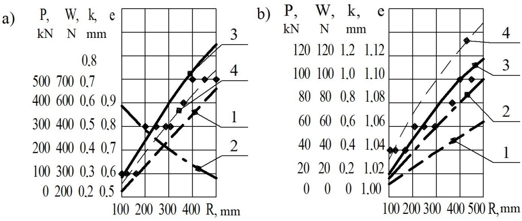
Fig. 1. Dependence on the wheel radius for linear a)
and point contact b)
(points show the reference values of
the rolling friction coefficients):
1
– wheel pressure restraining force;
2 – coefficient of
hysteresis losses;
3
– rolling friction
coefficient; 4
– rolling resistance coefficient
For
this, the
load
on the
wheels with
the radii
 mm and
 mm can
be divided
on two
wheels in
the ratio
mm can
be divided
on two
wheels in
the ratio
 .
.
Dependences of the coefficients
of rolling friction, loading and rolling resistance of the wheel and
the total resistance of the wheels are shown in Fig. 2
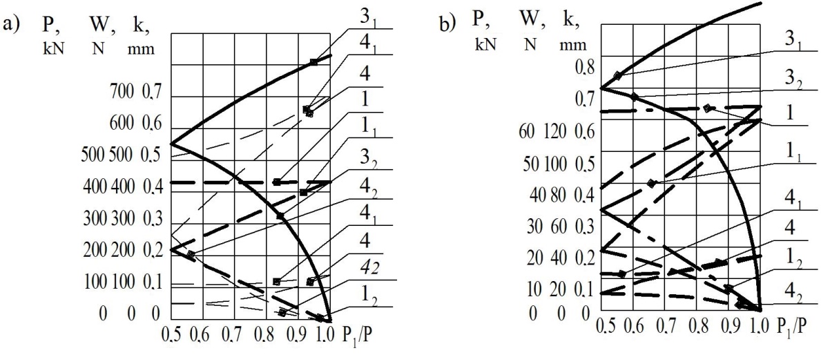
Fig. 2. Dependences of the ratio of
the applied forces for linear
(a)
and point (b)
contacts: 1, 11,
12
– total value of the pressing force
and the force acting on
each wheel, 31,
32
– rolling friction coefficients;
4,
41,
42
– total rolling
resistance value and rolling resistance of each wheel;
lower
position of curves for wheel mm, upper for wheel
 mm.
mm.
Analytic
dependencies (6) and (7) are used to determine the coefficients
rolling friction, so it is possible to restore one lacuna in the
reference literature. Losses in roller bearings are found by the
coefficient of friction reduced to the shaft (ball ,
roller
,
roller
 [2]). However, this does not take into account, which race is
rotating, inner or outer one.
[2]). However, this does not take into account, which race is
rotating, inner or outer one.
Assuming that the deviation in
the coefficient is negligible, it should be borne in mind that the
number of locally positioned bearings may be significant (conveyors,
vehicles), as well as an increase in the efficiency from 0.99 to
0.995 per ten bearings gives it an increase in more than 5%.
2. Ball
bearings.
The tasks
to be
clarified when
calculating
resistance:
1) To
take into
account the
difference in
the coefficients
of rolling
friction during
rolling of
the ball
on the
inner and
outer races,
since for
calculating
their size
we take
them equal, and
the tangential
force acting
on the
ball (Fig.
3, a) is
defined as
[8]
 ;
;
2) To take into account the
rotation of the race, since the special feature of the roller
bearings design is that the balls (rollers) pass different lines
during one revolution of the inner or outer race.
Under the
simplified scheme of the bearing, the problem is solved as follows.
If the outer race rotates at an angular velocity
 (Fig. 3, b), then the speed of point 1 as the point belonging to the
outer race will equal:
(Fig. 3, b), then the speed of point 1 as the point belonging to the
outer race will equal:
 , (12)
Where o, i,
b are the letters of the indices of sizes and speed of outer, inner
races and ball;
 – frequency of rotation of both inner and outer races.
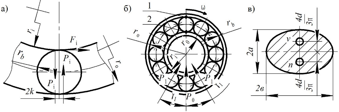
Fig. 3. Elements of bearings: a – scheme for
determining the tangential force during
the rotation of inner
race [1], b – scheme for determining the speed
of
points of outer race and ball; c – contact pattern
Naturally,
that the instantaneous velocity center of this race is located at
point 2 of the ball touch. Assuming that there is no slip between
the outer race and the ball, then .
.
The length
of the ball rolling track on the outer race
 ,
and on the inner race
,
and on the inner race
 and the length difference will be
 ,
that is, on this track there will be ball sliding on the inner race.
,
that is, on this track there will be ball sliding on the inner race.
In case of
rotation of the inner race with the fixed outer race the difference
 is evident that the ball will pass the outer race track that equals
the inner race track.
is evident that the ball will pass the outer race track that equals
the inner race track.
We find the load on the balls
based on their number [8]:
 . (13)
The force acting on the most
loaded ball is:
 . (14)
For further calculations, the
radius of the ball (without rounding to the standard one) and of the
rolling bearing track will be equal [8, 9]:
 ;
;
 .
.
For the
number of balls
 the load on the bearing
 (for example, if
 )
[8]:
)
[8]:
 , (15)
where
 is the angle between the balls (here
 ).
Based on this, the load on the side balls
).
Based on this, the load on the side balls
 ,
,
 . (16)
The values of the half-width of
contact patterns in formulas (9) and (11) are determined from
expressions (17) and (18). When rolling the ball on the inner ring:
 , (17)
where
 – is the coefficient, depending on the tangency ellipse equation
 .
In formulas (13) – (17)
.
In formulas (13) – (17)
 – outer bearing diameter;
 – inner bearing diameter;
 radius of the track of the inner race.
At
 for the most loaded ball, it is necessary to set optionally the
value of P,
and for the side balls
for the most loaded ball, it is necessary to set optionally the
value of P,
and for the side balls
 or
or
 depending on the number of balls.
When rolling the ball on the
outer race:
 , (18)
where
 is determined as a function;
 ;
;
 is the radius of the outer race track.
3.
Influence of resistance in bearings on wheel rolling resistance. Let
us consider two rolling bearings of one series, but of essentially
different sizes.
3.1. Ball
bearing of 304 series. Calculation
output data: bearing of 304 series,
 mm,
mm,
 mm, static load
 kN, average diameter
 mm,
mm,
 mm, number of balls
 at
at
 ,
,
 mm;
mm;
 mm;
mm;
 mm.
mm.
Half-width
contact pattern of the ball, loaded with force
 N, with the inner race
 mm for
 ,
with the outer race
,
with the outer race
 mm for
 .
Correspondingly, the side balls loaded by force
.
Correspondingly, the side balls loaded by force
 :
:
 mm;
mm;
 mm. Resistance to rolling of the most loaded ball: on the inner race
 N, with the rolling friction coefficient
 mm, on the outer race
 N with
 mm; two side balls on the inner race
 N with
 mm and
 N with
 mm.
mm.
Let us determine the work of
the rolling friction forces during one rotation of the inner and
outer races.
During rotation of the inner
race, Nm:
 ; (19)
During the
rotation of the outer race, Nm:
 (20)
(20)
Thus, during
the rotation of the inner race, the rolling friction force work
during one rotation equals
 Nm, in case of the outer race rotation
 Nm (1.55 times higher), and taking into account sliding
 Nm, that is, 6 times higher.
In this
case, the value of the conditional coefficient of friction reduced
to the shaft is equal to: during the rotation of the inner race
 ,
for the recommended value
,
for the recommended value
 ,
and during the rotation of the outer race
,
and during the rotation of the outer race
 .
.
3.2. Ball
bearing
of 2306 series.
Calculation output data for the
bearing of 2306 series:
 mm,
mm,
 mm, static load
 kN, roller diameter
 mm, roller length
 mm, number of rollers
 at
at
 bearing track radius on the inner race
 mm, track radius on the outer race
 mm.
mm.
The force acting on the most
loaded and side rollers is determined from formulas (15) and (16).
It was proved in [9] that if a
load is applied to a group of bodies according to the cosine law,
then to determine the resistance to their rolling, all loads can be
applied to one body, that is, the rolling resistance of all five
rollers on the inner race for the linear contact is determined from
the expression:
 , (21)
and on the outer race:
 . (22)
According to
formula (6), the rolling friction coefficient will be respectively
 mm,
mm,
 mm. The rolling resistance of rollers: on the outer race
 Н, N, and on the inner race
 N.
N.
Work of rolling and sliding
friction forces on the inner and outer races, Nm:

 (23)
(23)
for the
friction sliding coefficient of rollers on the inner race
 .
.
The motion
resistance coefficient is: during the rotation of the inner race
 ,
during the rotation of the outer race
,
during the rotation of the outer race
 ,
for the recommended value [9] for the wheel with up to 700 mm
diameter
,
for the recommended value [9] for the wheel with up to 700 mm
diameter
 .
.
4. Ball-bearing
slewing gear (SG). The formula for
determining the greatest pressure on the ball, given in [11],
contains two unknowns: the average diameter of the rolling circle
and the number of balls.
If the first unknown can be set
on the basis of constructive considerations, then the number of
balls can be set after finding their diameters. In addition, this
formula is acceptable only if the reaction from the moment does not
go beyond the support contour.
We propose finding the moment
of the friction forces in the following sequence.
4.1. The
slewing ring is broken, for example, into 10 sectors with a central
angle
 and for constructive reasons the average radius of the ball centers
is taken
and for constructive reasons the average radius of the ball centers
is taken

4.2. We apply the load to one
conditional ball in the sector, similar to the ball bearing (15), we
find the maximum vertical pressure on it from the moment, Nm:
 (24)
(24)
Under
the
known
value
of
vertical
pressure
 ,
the
pressure
on
the
balloon
will
be:
,
the
pressure
on
the
balloon
will
be:
 Nm,
(25)
Nm,
(25)
where
 is
the angle between the reaction of the ball and the vertical line
(usually
is
the angle between the reaction of the ball and the vertical line
(usually
 )
(Fig.
4).
)
(Fig.
4).
Maximum
pressures on conditional side balls, Nm:
 (26)
(26)
4.3.
Maximum
pressure
on
the
opposite
(left)
conditional
ball:
 Nm.
(27)
Nm.
(27)
The
pressure on the left conditional side balls is found in the same way
as for the right ones.
4.4.
After
the value
 ,
we roughly take the diameters of the ball
,
we roughly take the diameters of the ball
 .
.
4.5.
We
find
the
number
of
balls
in
one
sector
with
geometric
conditions:
 .
.
4.6.
Maximum
pressure
on
one
ball
of
the
right
sector
 and
the
ball
radius,
based
on
Hertz
contact
pressure
for
the
track
radius
and
the
ball
radius,
based
on
Hertz
contact
pressure
for
the
track
radius
 mm:
mm:
 Nm,
(28)
Nm,
(28)
where
 is the value depending on the ratio of tangible ellipse equation
factors
is the value depending on the ratio of tangible ellipse equation
factors
 ;
;
 – boundary contact stresses depending on the steel grade, contact
type and Brinell-hardness; for
– boundary contact stresses depending on the steel grade, contact
type and Brinell-hardness; for
 mm,
mm,
 (
( ;
;
 [4]).
[4]).
4.7. We find the final diameter
of the ball, while proceeding from conditions 4.4 and 4.6 and
determine the number of balls.
4.8.
Based
on the equations (25), (26), (27) and the number of balls, we
determine the pressure on one ball per sector, the rolling
resistance by the formula (7) of one of the balls of 10 sectors.
We
find the rolling resistance of
 balls
and total pressure as the sum of values obtained by the
formulas (25) and (27).
balls
and total pressure as the sum of values obtained by the
formulas (25) and (27).
We find the rotational
resistance coefficient as the ratio of the total rotational
resistance to the total pressure.
Calculations
are carried out according to the following data: the greatest moment
acting on the slewing ring
 kNm, the largest vertical reaction
 kN, the average diameter of the ball centers
 mm (
mm ( mm).
mm).
In
this case,
the vertical
pressure from
the moment,
taking into
account the
side balls
(24) will be
 kN, and
pressure on
the right
and left
conditional
balls (25) and
(27)
kN, and
pressure on
the right
and left
conditional
balls (25) and
(27)
 kN,
kN,
 kN. Having
taken the
ball diameter
kN. Having
taken the
ball diameter
 mm and
the maximum
pressure on
one ball,
we will
have:
mm and
the maximum
pressure on
one ball,
we will
have:
 kN,
kN,
where
is determined from geometric conditions
 .
Let us check the taken ball radius
.
Let us check the taken ball radius
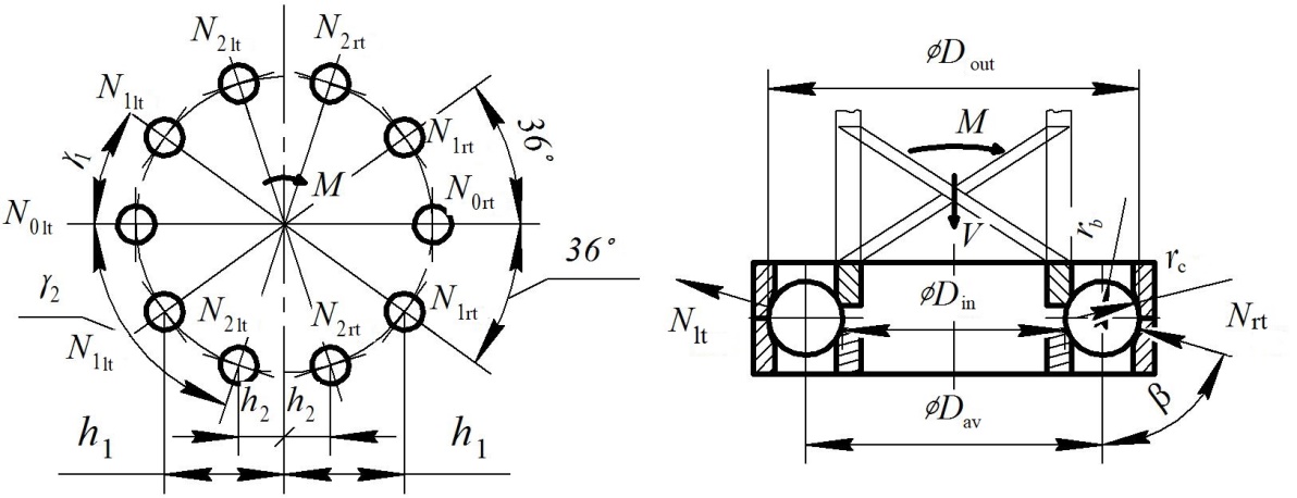
Fig.
4. Design diagram of
the ball-bearing SG
by the
theory of contact stresses provided that
 :
:
 Nm,
(29)
Nm,
(29)
where
 mm for
 MPa (surface hardened steel 45 [2]).
For
taking into account the number of balls in the sector and pressure
on the conditional central and side balls (26), we find the
half-width of the contact pattern:
 . (30)
The rolling
friction coefficient is determined by the formula (7), and the
rolling resistance subject to two rolling surfaces, i.e.
 .
.
The distribution of pressure
per ball on the ring length and the rolling resistance of each ball
in the form of graphs are shown in Fig. 5 [5, 12-13].
When adding
all the pressures on the balls and their resistance to rolling and
disision of
 kN by
kN by
 kN, we obtained the value of the reduced rotational resistance of
the crane
kN, we obtained the value of the reduced rotational resistance of
the crane
 that significantly exceeds the recommended value
 .
.
The reasons
for this discrepancy may be: a) irrelevance of the value adopted
here to the valid one; b) understated value
 during
the experiment.
during
the experiment.
It
can be
emphasized that
in the
examples of
SG calculations,
given in
[11, 12], the
coefficient
 is taken
in relation
to these
quantities, and
in [13]
is taken
in relation
to these
quantities, and
in [13] .
.
Let us find
the value of the rotational resistance coefficient, which falls on
sliding during rolling along the ring. Usually it is taken into
account only when moving along a cylinder ring. However, in the case
of ball contact with both the plane and the bearing
track, the contact pattern is not a point,
but the ellipse with the axes
 and
and
 the
length of which is determined from the Hertz contact deformation
formulas.
the
length of which is determined from the Hertz contact deformation
formulas.
The average
pressure per ball during its rotation by 3600
is
 kN. Herewith, the minor axis of the
ellipse is
kN. Herewith, the minor axis of the
ellipse is
 mm.
mm.
Concentrating
the pressure at 4 points, we find that the pressure at the points v
and n
(see Figure 3)
is
kN. In this
case, the vertical axis of the ellipse [4]:
 mm.
(31)
mm.
(31)
The distance
from these points to
is ,
i.e.
,
i.e.
 mm.
mm.
The
difference in
the distance
travelled by
one rotation
of the
ring is
 mm. For
 kN,
kN,
 (steel on
steel, no
lubrication),
the work
of sliding
friction forces
will be
(steel on
steel, no
lubrication),
the work
of sliding
friction forces
will be
 Nm. Expressing
the work
of normal
forces
Nm. Expressing
the work
of normal
forces
 through the
reduced
coefficient, we
can obtain
through the
reduced
coefficient, we
can obtain
 ,
wherefrom
,
wherefrom
 (32)
(32)
and is about
0.01 of the recommended value of the reduced rotational resistance
coefficient of the building cranes. However, it should be borne in
mind that the denominator of the formula defining
 ,
includes the average radius of the ball centres
,
includes the average radius of the ball centres
 The distribution of pressure per ball on the ring length and the
rolling resistance of each ball in the form of graphs are shown in
Fig. 5
The distribution of pressure per ball on the ring length and the
rolling resistance of each ball in the form of graphs are shown in
Fig. 5
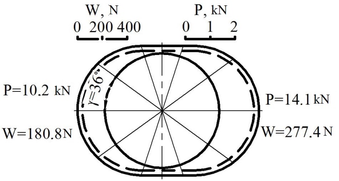
Fig. 5. Distribution of
pressures per one ball and resistance to its rolling along the ring
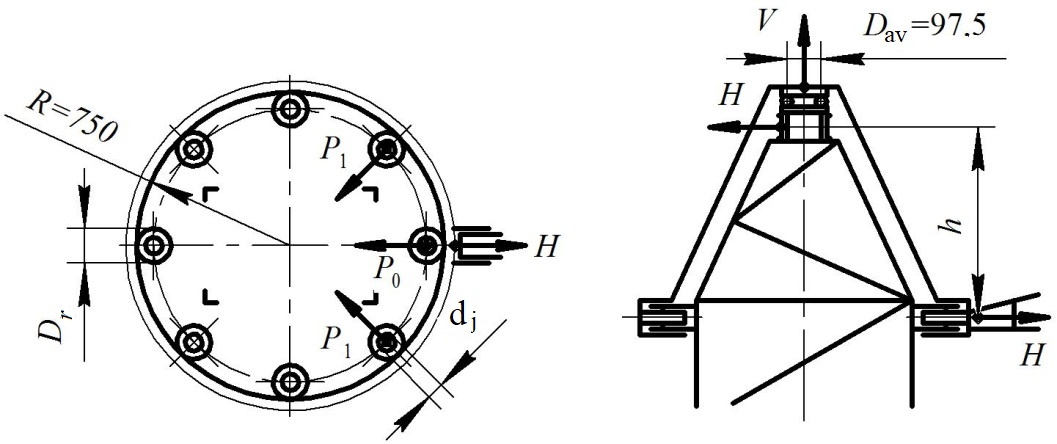
Fig. 6. Design diagram of the slewing gear of a
construction tower crane
with fixed rollers on roller bearings,
thrust bearing and top slide journal
5.1.
Calculation of support rollers. Load
on the roller, located on the line of force

 kN, the force acting on each of the two side rollers is the same and
is equal to
kN, the force acting on each of the two side rollers is the same and
is equal to
 kN.
kN.
For the
roller width
 mm and
 MPa (steel 75, mode of operation 5M), its radius is determined from
the Hertz contact forces formula:
MPa (steel 75, mode of operation 5M), its radius is determined from
the Hertz contact forces formula:
 , (33)
it is 130 mm.
Half-width of the contact
pattern
 , (34)
and it is 1.75 mm.
Rolling
coefficient of the side roller (6)
 mm, and that located on the horizontal axis
 mm.
mm.
Rolling resistance of three
rollers:
 N.
N.
Due to the
high pressure on the rollers and the impossibility of selecting the
appropriate roller bearing, it is possible to apply in the
construction tower cranes the bearings with friction sliding
coefficient and with the journal diameter
 mm.
mm.
Friction resistance in roller
journals:
 kN. (35)
For the top
journal diameter
 mm the sliding resistance in it
 kN. (36)
5.2.
Resistance in thrust bearing. According
to the value of static load on the bearing
 kN we take the bearing of 8216 series with
 mm,
mm,
 mm, ball diameter
 mm, number of balls
 ,
track radius
,
track radius
 mm.
mm.
When loading
one ball
 kN, the half-width of the contact pattern
(11)
kN, the half-width of the contact pattern
(11) mm
mm
 .
.
The rolling
friction coefficient according to formula (7) is
 mm.
mm.
The rolling
resistance of 20 balls
 N. The ball sliding resistance coefficient in accordance with (32)
for
(thick lubrication)
N. The ball sliding resistance coefficient in accordance with (32)
for
(thick lubrication)
 and for its rolling resistance value is
 N, which is about half of the rolling resistance and requires
consideration when calculating the units with thrust bearings.
N, which is about half of the rolling resistance and requires
consideration when calculating the units with thrust bearings.
The total
moment of frictional forces during the turning of a construction
crane with a fixed tower consists of the resistances:
rolling
of support rollers
771 N (20% of
the total);
– in
the roller journals 17 N (0.4% of the total);
– in
the top journal 21 N (0.5% of the total);
– in
the support roller from the rolling of balls 2 160 N (56% of the
total) and their sliding 900 N (23% of the total) for a total
rotational resistance value of 3 870 N.
6.
Rotational resistance of SG rollers with stationary and fixed
rollers. In some construction cranes,
the support rollers are stationary (Fig. 7, a) or movable (Fig. 7,
b). Load per a roller
 .
.
It is obviously that for
cylindrical rollers, the values of the maximum contact stresses will
be different, and the diameters of the rollers and their rolling
support on the slewing ring will have different values as well.
For
calculations we take the same radius, as in the previous example,
 mm, the horizontal reaction is equal to
 kN, the boundary contact stress is
MPa, the roller width
kN, the boundary contact stress is
MPa, the roller width
 .
.
The radius
of the roller for the diagram a
(Fig. 7) can be found from formula (33), by replacing
with
 .
According to the taken values
.
According to the taken values
 mm, the journal radius is taken to be equal to
 mm for cases a
and b
(Fig. 7).
mm for cases a
and b
(Fig. 7).
The radius
of the roller for the diagram b
(Fig. 7) can be found by the same formula (33) in the case of
change of the sign under the radical to the inverse, and it will be
equal to
 mm.
mm.
Half-width
of the contact patterns is found by the formula (34) with the change
of the sign to the inverse, according to the diagram b
before
(see Figure 7).
Half-width of the contact
patterns (Fig. 7):
according to
the diagram a
 mm, according to the diagram b
–
mm, according to the diagram b
–
 mm;
mm;
rolling
resistances of the two rollers are respectively
 N and
N and
 N.
N.
The
resistance in the journals of the two rollers according to the first
and second diagrams
is
 kN, that is more than two orders higher than the rolling resistance
of rollers.
kN, that is more than two orders higher than the rolling resistance
of rollers.
Originality
and practical value. The
paper proposes to use analytical dependences to determine the
reduced rotational resistance coefficient for linear and point
contacts using Hertz contact deformations theory and Tabor partial
analytic dependencies. The obtained dependencies will allow to
design new types of slewing gear assemblies of the construction
machines and to find additional rotational supports, which depend on
the overall dimensions, shape and type of material from which the
components of the assembly are made and do not contain any empirical
data.
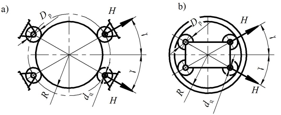
Fig. 7. Design diagram of the slewing gear of cranes:
a – with stationary
rollers; b
– with moving rollers
Conclusions
The analysis of the
dependencies and graphs obtained makes it possible to draw the
following conclusions and suggestions:
rolling friction coefficient
and rolling resistance of the crane type wheels practically linearly
depends on the wheel radius, and the coefficient of hysteresis
losses linearly decreases from 0.9 to 0.6 per linear contact and
linearly increases from 1.01 to 1.06 per point contact;
the friction coefficient value
of rolling bearings, reduced to the shaft, depends on whether inner
or outer race rotates;
during the outer race rotation
on a different path, passed by a ball or a roller on the tracks of
the outer and inner races, the friction coefficient reduced to the
shaft, which falls on pure rolling, is 1.3...1.5 times higher than
its value during the inner race rotation, and taking into account
the sliding of balls or rollers on the inner race, it is 4...6 times
higher than its size in ball bearings and 3 ... 4 times higher –
in roller bearings;
due to the high value of
friction in case of outer race rotation, during the design of
rolling assemblies, it is necessary to avoid such solutions, and, if
it is impossible, to take into account this fact both for the
determination of resistance and for the lubrication of the assembly;
the given value of the
resistance of the construction crane with the ball-bearing sewing
gear is obtained analytically, is 70% higher than the one
recommended by supplier;
In case of construction cranes
with a turning tower, the greatest resistance to rotation falls on
support rollers (about 80%).
LIST OF REFERENCE LINKS
Бондаренко,
Л. М. Деформаційні опори в машинах / Л.
М. Бондаренко, М. П. Довбня, В. С. Ловєйкін.
– Дніпропетровськ : Дніпро-VAL, 2002. – 200
с.
Бондаренко,
Л. М. Уточнення розрахункової схеми
навантаження групи тіл кочення / Л. М.
Бондаренко, С. В. Ракша, М. Г. Брильова
// Підйомно-транспортна техніка. – 2005.
– № 1. – С. 47–52.
Влияние
сопротивлений качению на динамику
механизмов подъема транспортирующих
машин /
В. М. Богомаз, Л. Н. Бондаренко,
О. В. Богомаз, М. Г. Брылева // Наука та
прогрес транспорту. – 2018. – № 2 (74). –
С. 124–132. doi: 10.15802/stp2018/130441
Грузоподъёмные
машины : учебник для вузов / М. П.
Александров, Л. Н. Колобов, М. А. Лобов
[и др.]. – Москва : Машиностроение, 1986. –
400 с.
Джонсон,
К. Механика контактного взаимодействия
/ К. Джонсон. – Москва : Мир, 1989. – 510 с.
Иванов,
М. Н. Детали машин. Курсовое проектирование
/ М. Н. Иванов, В. Н. Иванов. – Москва :
Высш. школа, 1975. – 551 с.
Ковальський,
Б. С. Вопросы передвижения мостовых
кранов / Б. С. Ковальський
; Восточноукр. нац. ун-т. – Луганск
: [б. и.], 2000. – 63 с.
Кожевников,
С. Н. Теория механизмов и машин / С. Н.
Кожевников. – Москва : Машиностроение,
1969. – 584 с.
Писаренко,
Г. С. Справочник по сопротивлению
материалов / Г. С. Писаренко, А. П. Яковлев,
В. В. Матвеев. – Киев : Наук. думка,
1988. – 736 с.
Расчеты
грузоподъёмных и транспортирующих
машин / Ф. К. Иванченко, В. С. Бондарев,
Н. Т. Колесник, В. Я. Барабанов. – Киев :
Выща школа, 1975. – 520 с.
Справочник
по кранам : в 2 т. / М. П. Александров, М.
М. Гохберг, А. А. Ковин [и др.] ; под общ.
ред. М. М. Гохберга. – Ленинград
: Машиностроение, 1988. –
Т. 2. –
559 с.
Технологічні
процеси під час відновлення
опорно-обертального пристрою будівельних
кранів /
А. М. Храмцов, В. М. Богомаз,
І. М. Щека, І. Є. Крамар // Проблеми та
перспективи розвитку залізничного
транспорту : тези доп. 77 Міжнар.
наук.-практ. конф. (Дніпро, 11–12 трав.
2017 р.) / Дніпропетр. нац. ун-т залізн.
трансп. ім. акад. В. Лазаряна.
– Дніпро, 2017. – С.
315–316.
Akhavian,
R. Remote Monitoring of Dynamic Construction Processes Using
Automated Equipment Tracking / R. Akhavian, А.
Behzadan // Construction Research Congress (May 21–23, 2012). –
West Lafayette, Indiana, United States, 2012. – Р.
1360–1369. doi: 10.1061/9780784412329.137
Criteria
for the selection of sustainable onsite construction equipment / М.
Waris, M. Shahir Liew,
M. F. Khamidi, А.
Idrus // International Journal of Sustainable Built Environment. –
2014. – Vol. 3. –
Іss. 1.
– Р. 96–110. doi:
10.1016/j.ijsbe.2014.06.002
Eldredge,
K. R. The mechanism of roiling friction. I. The plastic range. II.
The elastic range / K. R. Eldredge, D. Tabor // Wear.
– 1958. – Vol. 1. – Іss.
5. – Р. 452. doi:
10.1016/0043-1648(58)90178-9
Holt,
G. Analysis of interrelationships among excavator productivity
modifying factors / G. Holt, D. Edwards // International Journal of
Productivity and Performance Management. – 2015. – Vol. 64.
– Іss. 6.
– Р. 853–869. doi:
10.1108/IJPPM-02-2014-0026
Pries,
F. Innovation in the construction industry: the dominant role of the
environment / F. Pries, F. Janszen // Construction Management and
Economics. – 1995. – Vol. 13. –
Іss. 1.
– Р. 43–51.
doi :
10.1080/01446199500000006
Slemenmeyer,
H. Bearings for large capacity crane applications / H. Slemenmeyer,
S. Aaronson // SAE Technical Paper Series. – 1983. doi:
10.4271/831373
Su,
X. Improving Construction Equipment Operation Safety from a
Human-centered Perspective / Х. Su,
J.
Pan, М. Grinter // Procedia Engineering.
– 2015. – Vol. 118. – Р. 290–295.
doi: 10.1016/j.proeng.2015.08.429
Takahashi,
H. Measurement of the rolling element load distribution in turntable
bearings / H. Takahashi,
H. Omary // SAE Technical Paper Series.
– 1985. doi: 10.4271/850762
Yip,
H. Predicting the maintenance cost of construction equipment:
Comparison between general regression neural network and Box–Jenkins
time series models / Н. Yip, H. Fan, Y.
Chiang // Automation in Construction. – 2014. – Vol. 38. – Р.
30–38. doi: 10.1016/j.autcon.2013.10.024
Л. М. Бондаренко1,
О. П. ПосмітюхА2*,
К. Ц. Главацький3.
1Каф. «Прикладна
механіка та матеріалознавство»,
Дніпровський національний університет
залізничного
транспорту імені академіка
В. Лазаряна, вул. Лазаряна, 2, Дніпро,
Україна, 49010, тел. +38(056)3731518,
ел. пошта
bondarenko-l-m2015@yandex.ua,
ORCID 0000-0002-2212-3058
2*Каф. «Прикладна
механіка та матеріалознавство»,
Дніпровський національний університет
залізничного
транспорту імені академіка
В. Лазаряна, вул. Лазаряна, 2, Дніпро,
Україна, 49010, тел. +38 (066) 150 95 00,
ел. пошта
AleksandrP@3g.ua, ORCID
0000-0002-9701-3873
3Каф. «Прикладна
механіка та матеріалознавство»,
Дніпровський національний університет
залізничного
транспорту імені академіка
В. Лазаряна, вул. Лазаряна, 2, Дніпро,
Україна, 49010, тел. +38 (095) 816 99 90,
ел. пошта kazimir.glavatskij@gmail.com
, ORCID
0000-0003-0921-9845
АНАЛІТИЧНЕ ВИЗНАЧЕННЯ ПРИВЕДЕНОГО
КОЕФІЦІЄНТА ОПОРУ
ОБЕРТАННЮ МЕХАНІЗМІВ
ПОВОРОТУ БУДІВЕЛЬНИХ МАШИН
Мета.
Проектування нових зразків будівельних
машин тісно пов’язане з розробкою
механізмів повороту, а ті, в свою чергу,
мають привід, потужність та габарити
якого залежать від опору повороту та
приведеного коефіцієнта тертя у вузлах.
Відсутність аналітичних залежностей
для визначення приведеного коефіцієнта
тертя обертанню будівельних машин,
по-перше, обмежує можливості конструктора
у виборі матеріалів, а по-друге, не
дає можливості приймати оптимальні
конструктивні рішення. Тому мета статті
– знайти аналітичні рішення для
визначення опорів обертанню в механізмах
повороту будівельних машин, що дозволяє
проектувати досконаліші механізми й
машини у цілому. Існуючі методики
спираються на емпіричні залежності та
експериментальні коефіцієнти, що
зменшують точність підрахунків,
збільшують габарити та вартість робіт.
Пропонується підвищити точність та
спростити процес визначення опору
повороту й величину приведеного
коефіцієнта опору обертанню будівельних
баштових кранів.
Методика. Досягти
поставленої мети можна за допомогою
аналітичних залежностей для визначення
коефіцієнтів тертя кочення за лінійного
й точкового контактів. Це дозволить
точніше знайти величину коефіцієнта
опору, а конструктору під час розрахунків
вжити цілеспрямованих заходів щодо
його зменшення, використовуючи механічні
константи матеріалів вузлів кочення
і їх геометричні параметри. Розрахунок
ґрунтується на теорії контактних
деформацій Герца й теорії плоского
руху точок тіла. Результати.
Отримані залежності дозволять аналітично
знайти опір кочення роликів у будівельних
машинах із нерухомою й обертовою
колонами, із круговими поворотними
пристроями, а також у кулькових і
роликових опорно-поворотних кругах.
З’ясовані значення коефіцієнтів опору
обертанню для деяких їх типів механізмів
дають близькі значення з рекомендованими,
а для деяких – істотно відрізняються
і вимагають їх уточнення у довідкових
величинах. Наукова
новизна роботи полягає
у використанні аналітичних залежностей
для визначення приведеного коефіцієнта
опору обертанню за лінійного і точкового
контактів із використанням теорії
контактних деформацій Герца та частково
аналітичних залежностей Табора.
Практична значимість.
Отримані залежності дозволять проектувати
нові типи вузлів обертання механізмів
повороту будівельних машин і виявляти
додаткові опори обертанню.
Ключові слова: будівельна
машина; опір; обертання; поворот;
поворотний круг; рейка; тертя кочення
Л. Н. Бондаренко1,
А. П. ПосмИтюхА2*,
К. Ц. Главацкий3
1Каф. «Прикладная
механика и материаловедение», Днипровский
национальный университет железнодорожного
транспорта имени академика В. Лазаряна,
ул. Лазаряна, 2, Днипро, Украина, 49010, тел.
+38 (056) 373-15-18,
эл. почта
bondarenko-l-m2015@yandex.ua,
ORCID 0000-0002-2212-3058
2*Каф. «Прикладная
механика и материаловедение», Днипровский
национальный университет железнодорожного
транспорта имени академика В. Лазаряна,
ул. Лазаряна, 2, Днипро, Украина, 49010, тел.
+38 (066) 150 95 00,
эл. почта AleksandrP@3g.ua,
ORCID 0000-0002-9701-3873
3Каф. «Прикладная
механика и материаловедение», Днипровский
национальный университет железнодорожного
транспорта имени академика В. Лазаряна,
ул. Лазаряна, 2, Днипро, Украина, 49010, тел.
+38 (095) 816 99 90,
эл. почта
kazimir.glavatskij@gmail.com, ORCID
0000-0003-0921-9845
АНАЛИТИЧЕСКОЕ ОПРЕДЕЛЕНИЕ приведенного
коэффициента
сопротивления вращению
механизмов поворота
СТРОИТЕЛЬНЫХ МАШИН
Цель. Проектирование
новых образцов строительных машин
тесно связано с разработкой механизмов
поворота, а те, в свою очередь, имеют
привод, мощность и габариты которого
зависят от сопротивления поворота и
приведенного коэффициент трения в
узлах. Отсутствие аналитических
зависимостей для определения приведенного
коэффициента трения вращению строительных
машин, во-первых, ограничивает возможности
конструктора в выборе материалов, а
во-вторых, не дает возможности принимать
оптимальные конструктивные решения.
Поэтому цель статьи – найти аналитические
решения для определения сопротивлений
вращению в механизмах поворота
строительных машин, которые позволят
проектировать более совершенные
механизмы и машины в целом. Существующие
методики опираются на эмпирические
зависимости и экспериментальные
коэффициенты, уменьшающие точность
подсчетов, увеличивающие габариты и
стоимость работ. Предлагается повысить
точность и упростить процесс определения
сопротивления поворота и величину
приведенного коэффициента сопротивления
вращению строительных башенных кранов.
Методика.
Достичь поставленной цели можно с
помощью аналитических зависимостей
для определения коэффициентов трения
качения при линейном и точечном
контактах. Это позволит точнее найти
величину коэффициента сопротивления,
а конструктору при расчетах принять
целенаправленные меры по его уменьшению,
используя механические константы
материалов узлов качения и их
геометрические параметры. Расчет
основывается на теории контактных
деформаций Герца и теории плоского
движения точек тела. Результаты.
Полученные зависимости позволят
аналитически найти сопротивление
качению роликов в строительных машинах
с неподвижной и вращающейся колоннами,
с круговыми поворотными устройствами,
а также в шариковых и роликовых
опорно-поворотных кругах. Найденные
значения коэффициентов сопротивления
вращению для некоторых типов механизмов
дают близкие значения с рекомендованными,
а для некоторых – существенно отличаются
и требуют их уточнения в справочных
величинах. Научная
новизна работы
заключается в использовании аналитических
зависимостей для определения приведенного
коэффициента сопротивления вращению
для линейного и точечного контактов с
использованием теории контактных
деформаций Герца и частично аналитических
зависимостей Табора. Практическая
значимость. Полученные
зависимости позволят проектировать
новые типы узлов вращения механизмов
поворота строительных машин и выявлять
дополнительные опоры вращению.
Ключевые слова: строительная
машина; сопротивление; вращения; поворот;
поворотный круг; рельс; трение качения
REFERENCES
Bondarenko,
L. M., Dovbnia, M. P., & Loveikin, V. S. (2002).
Deformatsiini opory v mashynakh.
Dni-propetrovsk: Dnipro-VAL. (in
Ukrainian)
Bondarenko,
L. M., Raksha, S. V., & Brylova, M. H. (2005). Utochnennia
rozrakhunkovoi skhemy navantazhennia hrupy til kochennia.
Pidiomno-transportna tekhnika, 1, 47-52. (in
Ukrainian)
Bohomaz,
V. M., Bondarenko, L. M., Bohomaz, O. V., & Brylyova, M. G.
(2018). Effect of resistance to rolling on the dynamics of the
lifting mechanisms of the transporting mac. Science and
Transport Progress. 2(74), 124-132.
doi: 10.15802/stp2018/130441 (in
Russian)
Aleksandrov,
M. P., Kolоbov,
L. N., Lobov,
M. A.
Nikolskaya, T.
A., & Polkovnikov,
V. S. (1986).
Gruzopodemnye mashiny: Uchebnik dlya vuzov. Moscow:
Mashinostroenie. (in
Russian)
Dzhonson,
K. (1989). Mekhanika kontaktnogo
vzaimodeystviya. Moscow: Mir.
(in Russian)
Ivanov,
M. N., & Ivanov, V. N. (1975).
Detali mashin. Kursovoe proektirovanie.
Moscow: Vysshaya
shkola. (in
Russian)
Kovalskiy,
B. S. (2000). Voprosy peredvizheniya
mostovykh kranov. Lugansk. (in
Russian)
Kozhevnikov,
S. N. (1969). Teoriya mekhanizmov i
mashin. Moscow:
Mashinostroenie. (in
Russian)
Pisarenko,
G. S., Yakovlev, A. P., & Matveev, V. V. (1988). Spravochnik
po soprotivleniyu materialov. Kiev:
Naukova dumka. (in
Russian)
Ivanchenko,
F. K., Bondarev, V. S., Kolesnik, N. P., & Barabanov, V. Y.
(1975). Raschety gruzopodemnykh i
transportiruyushchikh mashin. Kiev:
Vishcha shkola. (in
Russian)
Aleksandrov,
M. P., Gokhberg, M. M., Kovin, A. A., & Gokhberg, M. M. (Ed).
(1988). Spravochnik po
kranam
(Vol. 1-2). Leningrad:
Mashinostroenie. (in
Russian)
Khramtsov,
A. M., Bohomaz, V. M., Shcheka, I. M., & Kramar, I. Y. (2017).
Tekhnolohichni protsesy pid chas vidnovlennia oporno-obertalnoho
prystroiu budivelnykh kraniv.
The Problems and
Prospects of railway transport: 77th
International scientific and practical conference.
Dnipro:
Dnipropetrovsk National
University of Railway Transport named after Academician V.
Lazaryan. (in Ukrainian)
Akhavian,
R., & Behzadan, A. H. (2012). Remote Monitoring of Dynamic
Construction Processes Using Automated Equipment Tracking.
Construction Research Congress 2012.
West Lafayette, Indiana, United States.
doi: 10.1061/9780784412329.137 (in English)
Waris,
M., Shahir Liew, M., Khamidi, M. F., & Idrus, A. (2014).
Criteria for the selection of sustainable onsite construction
equipment. International Journal of
Sustainable Built Environment, 3(1),
96-110. doi: 10.1016/j.ijsbe.2014.06.002 (in English)
Eldredge,
K. R., & Tabor, D. (1958). The mechanism of rolling friction.
I. The plastic range. II. The elastic range. Wear,
1(5), 452.
doi: 10.1016/0043-1648(58)90178-9 (in English)
Holt,
G. D., & Edwards, D. (2015). Analysis of interrelationships
among excavator productivity modifying factors.
International Journal of Productivity and Performance Management,
64(6), 853-869.
doi: 10.1108/ijppm-02-2014-0026 (in English)
Pries,
F., & Janszen, F. (1995). Innovation in the construction
industry: the dominant role of the environment. Construction
Management and Economics, 13(1), 43-51.
doi: 10.1080/01446199500000006 (in English)
Siemensmeyer,
H., & Aaronson, S. F. (1983). Bearings for Large Capacity Crane
Applications. SAE Technical Paper Series. doi:
10.4271/831373 (in English)
Su,
X., Pan, J., & Grinter, M. (2015). Improving Construction
Equipment Operation Safety from a Human-centered Perspective.
Procedia Engineering, 118, 290-295.
doi: 10.1016/j.proeng.2015.08.429 (in
English)
Takahashi,
H., & Omory, T. (1985). Measurement of the Rolling Element Load
Distribution in Turntable Bearings. SAE Technical Paper
Series. doi: 10.4271/850762 (in
English)
Yip,
H., Fan, H., & Chiang, Y. (2014). Predicting the maintenance
cost of construction equipment: Comparison between general
regression neural network and Box–Jenkins time series models.
Automation in Construction, 38, 30-38.
doi: 10.1016/j.autcon.2013.10.024 (in
English)
Received:
Sep. 06, 2018
Accepted:
Jan. 16, 2019