ISSN
2307–3489 (Print), ІSSN
2307–6666
(Online)
Наука
та прогрес транспорту. Вісник
Дніпропетровського
національного університету залізничного
транспорту, 2019,
№ 1
(79)
рухомий
склад і тяга поїздів
UDC
629.463.65.015:625.1.032
A.
O. shvets1*,
О. О. BOLOTOV2*
1*Dep.
«Theoretical and Structural Mechanics», Dnipro National University
of Railway Transport
named after Academician V. Lazaryan,
Lazaryan St., 2, Dnipro, Ukraine, 49010,
tel. +38 (050) 214 14 19,
e-mail angela_Shvets@ua.fm, ORCID 0000-0002-5537-6617
2*BRL
DSRS, Dnipro National University of Railway Transport named after
Academician V. Lazaryan,
Lazaryan St., 2, Dnipro, Ukraine, 49010,
tel. +38 (097) 977 57 08, e-mail bolaks@i.ua,
ORCID
0000-0002-0807-0340
INFLUENCE
OF LOADing FROM
THE AXLE OF a
gondola
car ON ITS DYNAMIC INDICATORS AND
railway track
Purpose.
Increasing the maximum loading from the car axle on the rails during
transportation of goods and the speed of movement of railway vehicles
will enhance the integration processes between the countries. In
order to ensure safe and reliable traffic at the railways it is
necessary to improve control, quantitative evaluation of the dynamic
loading of the rolling stock, which in the process of its operation
is a relevant scientific and technical problem. The purpose of this
work is to study the influence of the axle loading increase in
gondola cars, taking into account the possible speed increase on
their main dynamic indicators and indicators of interaction of
rolling stock and track. Methodology.
The study was carried out by the method of mathematical and computer
simulation of the dynamic loading of a gondola car using the model of
spatial oscillations of the coupling of five cars and the software
complex developed in the branch research laboratory of the dynamics
and strength of rolling stock (BRL DSRS).
The initial data for research are as follows: the movement of gondola
car of the model 12-532 with typical bogies of 18-100 at the speeds
ranging from 50 to 90 km/h in curves with radii of 350 and 600 m,
with superelevation of 130 and 120 mm, respectively. Findings.
The article analyzes the dynamic qualities of a rolling stock
using the example of gondola cars, the calculations are performed
using the package of applied programs with sufficient accuracy for
practice. During the theoretical studies and simulation, taking into
account the processes of freight car oscillation in case of
increasing the axle loading, the dependences of the main dynamic
parameters, taking into account the movement speed were obtained.
Originality. Originality of the work results lies in the study
of the influence of increasing the axle loading in gondola cars,
taking into account the possible movement speed increase on the
dynamic loading in order to solve the problem of forecasting the
rolling stock dynamics. The results of theoretical studies, taking
into account the movement speed in the curved track sections of small
and medium radius were obtained for the first time. Practical
value. The application of these results will contribute to
improving the traffic safety of freight cars and will improve the
technical and economic performance of railway transport.
Keywords:
cargo; gondola cars; dynamic indicators; curved track sections; axle
loading; interaction indicators; rolling stock and track;
gravity center; movement speed
Introduction
In accordance with the
established rules of loading, placing and fastening of cargoes in
cars should ensure: movement and operation safety of railway
transport; possibility of mechanization of loading and unloading
works; preservation of goods and cars.
In addition,
one of the main indicators of the efficiency of the car fleet
operation is the duration of the loading and unloading operations,
which depends on the fitting of freight points at the railway
stations and industrial enterprises with modern means of
mechanization. The planned reduction of the freight car turnover in
2017-2021, taking into account the improvement of the operation and
re-novation of the car fleet, is presented in Fig. 1 [3].
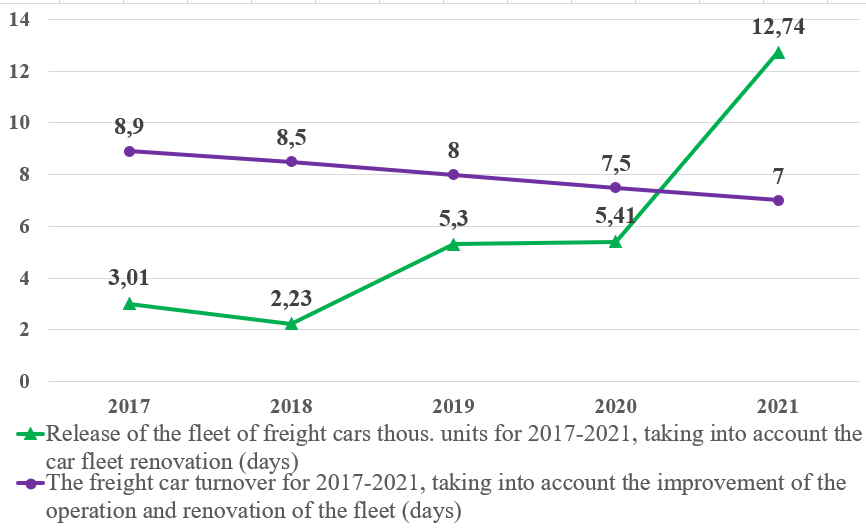
Fig.
1. Reduction of the freight car turnover
Due to the introduction of new
equipment for loading and unloading operations, it is possible to
reduce the level of car idle and to minimize it in future (Fig. 2).
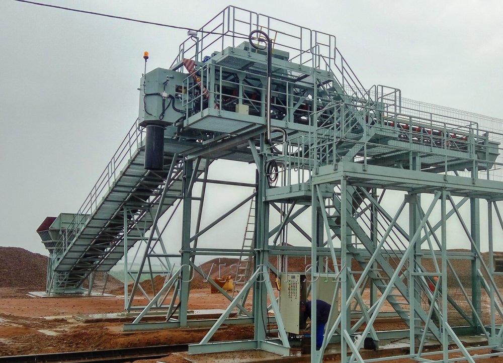
Fig.
2. Automated system of the dose loading of broken stone in
cars
For example, the automated
system of dose loading of broken stone in cars provides [1]:
– dose
loading of railway cars;
– uniform
loading of cars along the length;
– the
exclusion of time and labor costs arising from inadequate loading of
cars;
– automated
shipping accounting with print output of information and automated
control system of enterprise.
Safety performance during
transportation of bulk cargo of open storage in accordance with the
requirements of the Rules for the transportation of bulk cargo and
the Rules for the transportation of goods in open cars remains the
main task of the transport industry enterprises. As it is known,
depending on the method of loading the gondola cars with bulk cargo,
the form of cargo inequalities may be different (Fig. 3). In
accordance with clause 5 of the Rules for the transportation of
goods in open cars, one should in all cases level the cargo surface
[9, 12, 13].
а
b
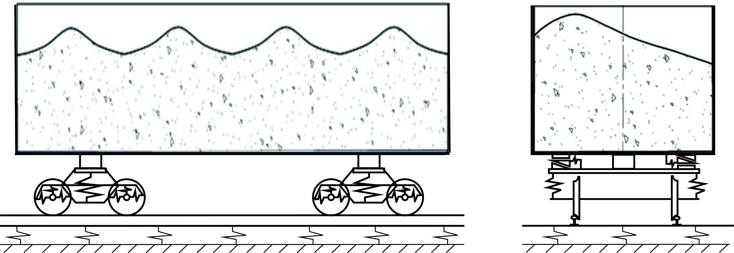
Fig.
3. The
form of cargo inequality:
а
–
longitudinal;
b
–
transverse
In order to level the cargo, the
most often nonmechanized method is used, which affects the idle
increase of gondola cars under freight operations, as well as
increase of the total transportation cost. In addition, manual
leveling can lead to accidents involving the risk of person`s
falling from height.
The leveling construction (Fig.
4) should allow the leveling of the bulk cargo, regardless of the
form of its position in the gondola car. The proposed designs of
rotary and screw device for the mechanization of bulk cargo leveling
in gondola cars have no analogues in domestic and world practice
[9].

Fig. 4. The device
for bulk cargo leveling
in gondola cars of the UkrDURT system
Each of them has its advantages
and disadvantages, namely:
– rotary
leveler has a lower mass and a significantly lower cost, but it can
only work with cargoes of relatively small bulk density and
satisfactory flowability;
– screw
leveler, which has greater material consumption and price, makes it
possible to mechanize the leveling of heavy cargoes with bad
flowability.
In addition, the loading should
be carried out in accordance with the current technical
specifications. Determination of the displacement of the load
gravity center relative to the railway car symmetry axes using the
car scales (Figure 5) allows us to quickly detect dangerous
deviations in the car stability and thus significantly increase
safety during the train movement [4].
Where it is necessary to reduce
the labour intensity, minimize the influence of human factor, reduce
the time spent for the inspection of cars, the appropriate solution
is to automatically scan and check the contents of cars involving
operator only in the case of alarm signals from the control system.

Fig. 5.
Computerized car scales for weighing
in static mode
The hardware-software complex
for controlling the car loading is intended for automatic 3D
scanning of gondola cars when moving in order to evaluate the level
of car volume loading, the uniformity of cargo distribution, cargo
volume, detect foreign objects, as well as for other functions in
the interests of production services, logistics and safety (Fig. 6)
[2].
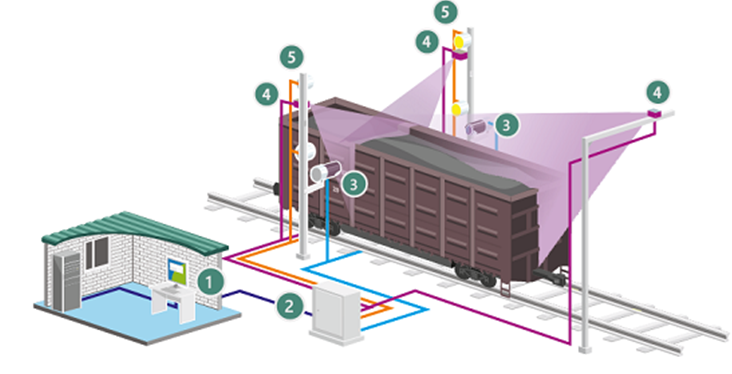
Fig. 6.
Hardware-software complex for controlling the car loading:
1
– computer with ARSCIS.Scanner software; 2
–ARSCIS.Scanner box; 3
– video cameras for detection;
4
– scanner of dimensions; 5
– spotlights
Automation of visual control of
the car contents provides:
– reducing
the time and labor cost for car control operations;
– minimization
of human factor influence;
– safety
improvement of the railway freight transportations;
– reduction
of losses due to underloading/overloading of cars;
– products
thievery prevention by railway transport.
The main functions of the
hardware and software complex are as follows:
– car and
cargo scanning using industrial laser sensors;
– construction
of a three-dimensional model of the car (and its contents) and its
analysis;
– determining
the level of car loading;
– detection
of foreign objects in an empty car;
– control
of the distribution evenness of bulk cargo in a car;
– cargo
volume evaluation in a car;
– detection
of loading errors (overloading, underloading, unevenness).
The leading domestic developer
of unloading systems for unloading bulk cargoes from the railway
transport and the largest producer of technological equipment, which
is the part of unloading complexes, is Dniprovazhmash PJSC (Fig. 7)
[15].
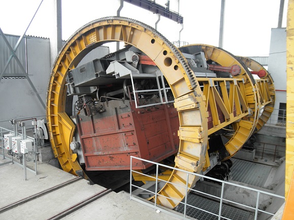
Fig.
7. Stationary rotary car dumper
VRS-93, VRS-93-110
Stationary
rotary car dumpers, which are produced by Dniprovazhmash PJSC, are
intended for unloading of gondola cars with bulk cargo with carrying
capacity
 t by means of gondola cars overturning in a rotary car dumper.
Composite application of modern
innovative technologies in railway transport will allow the
preservation of cars, reducing their idle time, releasing a
significant number of workers from heavy manual operations and
obtaining significant economic benefits.
Purpose
The State Administration of
Railway Transport of Ukraine established the maximum loading from
the car axle on the rails when transporting the freights destinated
to individual European countries and border crossings along the
track 1520 mm from 20 to 24.5 tons by the telegram dated November 7,
2011, No. CZM-12/2074 according to the Minutes of the meetings on
the harmonization of the volumes of the transportation conditions.
Increasing the permissible
loading on the car axle, with simultaneous increase in the speed of
the railway vehicles, will strengthen the integration processes with
the countries of Europe and Asia. The application of modern railway
innovative technologies described above makes it possible to
increase axle loading, but leads to the need for improved control,
quantitative evaluation of the dynamic loading of rolling stock to
ensure safe and reliable connection at the railways.
The limit axle loading for
freight cars of 23.5 tons per axle was taken into account as one of
the main prerequisites for determining the permissible speeds of
rolling stock, the order and terms for the designation of repair and
track works and labor standards for maintenance of the track and
artificial structures. Increasing the axle loading, in turn, leads
to the failure rate increase of the rails due to defects of
contact-fatigue nature and the deterioration of the track condition.
Therefore, in the design process of rolling stock quantitative
evaluation of dynamic loadings is a relevant scientific and
technical problem [5, 14, 18–22].
The article is aimed to study
the influence of increasing the axle loading in gondola cars, taking
into account the possible increase in the movement speed on their
main dynamic indicators and interaction indicators of track and
rolling stock.
Methodology
During operation of trains,
primarily the ones with increased length and weight, particular
attention is paid to the evaluation of the dynamic performance of
vehicles, among which the most important is the indicator
characterizing the traffic safety of a vehicle – the stability
coefficient against derailment. For this purpose, the mathematical
models of spatial oscillations of the car (or group of cars) moving
in a train are used.
The models of rolling stock, as
a rule, represent the variations of the system of differential
equations in the second-order partial derivatives compiled according
to the Lagrange–d'Alembert principle, which correspond to the set
task. Using such models, the problem can be found analytically.
Mathematical modeling makes it possible to determine the dynamic
parameters of cars during their movement in straight and curved
track sections with real irregularities in the vertical and
horizontal planes, taking into account the actual wheel thread and
the rail head profile [6, 11, 16, 17].
The oscillations of a single car
and its interaction with the rail track are considered using quite
full calculation schemes. Fig. 8 shows the calculation scheme of the
freight car and shows positive directions for all displacements and
rotation angles, and the designation of the system bodies are given
in Table 1.
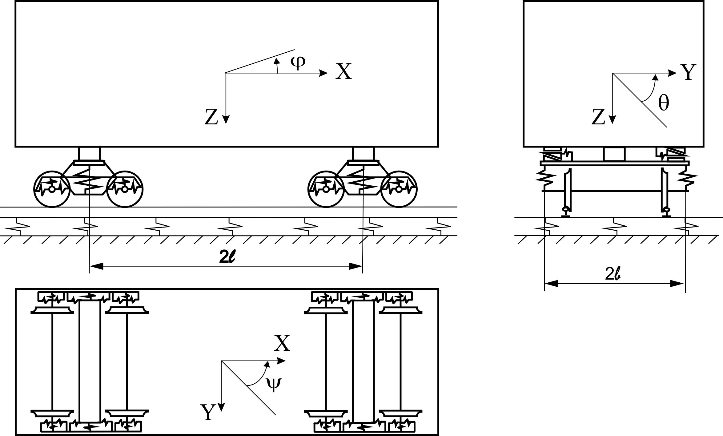
Fig. 8. Calculation
scheme of 4-axle gondola car
Table
1
System
bodies and their displacements
|
System
bodies
|
Displacement
|
|
Linear
along the axes
|
Angle
along the axes
|
|

|

|

|
|
|
|
|
Body
|

|

|

|

|

|

|
|
Bolsters
|

|

|

|

|

|

|
|
Side
frames
|

|

|

|

|

|

|
|
Wheel
sets
|

|

|

|

|

|

|
|
Rails
|
–
|

|

|
–
|
–
|
–
|
In Table 1
the displacements of the gravity center of the body along the
corresponding axes are indicated by
,
and
,
and rotation angles of the body relative to the main central inertia
axes – by
 ,
,
 ,
,
 .
Similar bolster displacements are provided by the index
.
Similar bolster displacements are provided by the index
 (
( bogie number), side frames – by the index
 (.
(. .–
left,
.–
left,
 right side of a car), wheel sets – by the index
 (
( – number of wheel set in a bogie), rails at the contact points
with the wheels
– number of wheel set in a bogie), rails at the contact points
with the wheels
 (rail displacements are provided only in two directions – along
the axes
and
).
Displacements of the wheels are indicated by the index
(rail displacements are provided only in two directions – along
the axes
and
).
Displacements of the wheels are indicated by the index
 .
.
The work [6] proposes a
mathematical model describing the spatial oscillations of the car
coupling in a train (Fig. 2), one rail carriage of which is
considered according to the fullest calculation scheme (called
"zero"), and the calculation schemes of neighboring cars,
depending on the task setting, are simplified as further is the
distance from the "zero" carriage on both sides.
A mechanical
system with 58 degrees of freedom is taken as a calculation scheme
of the "zero" carriage. The following values are taken as
generalized coordinates:


 (n=6, 7),
 (n=8, 9),
 (
( ),
),
 (
( ),
),
 (
( ),
),
 (
( ),
),
 (
( ),
),
 (
( ),
),
 (
( ),
),
 (
( ),
),
 (
( ),
),
 (
( ),
),
 (
( ),
),
 .
.
The cars, adjacent to the "zero"
one, are represented by a system with 12 degrees of freedom. In the
calculation schemes describing the oscillations of these cars, the
main features of freight car bogies are preserved – the side
frames lozenging.
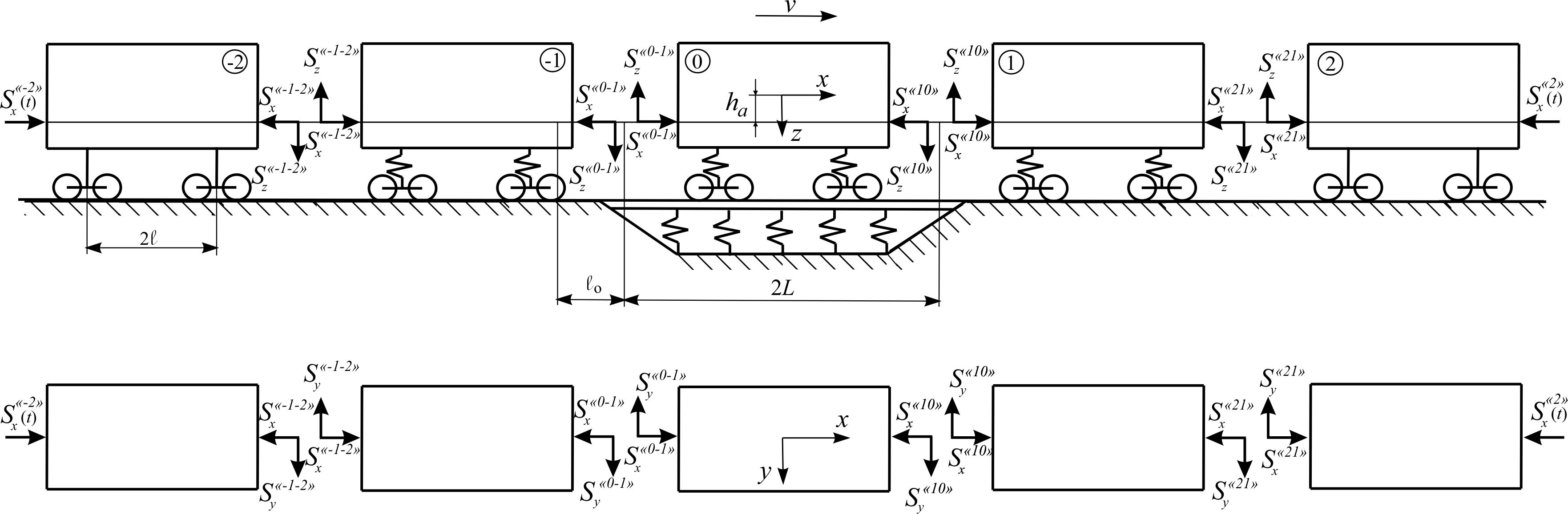
Fig.
9. The forces arising from the action
of longitudinal forces in
the auto-couplings of cars
During the
study of spatial oscillations of cars adjacent to the "zero"
one, considered by the simplified calculation scheme, the following
assumptions are introduced. It is assumed that the cars have
single-stage spring suspension. Each of them consists of eleven
solid bodies: a body, two bolsters, four side frames of the bogie
and four wheel sets. Unlike "zero" car, the track under
adjacent cars is considered to be absolutely rigid in the vertical
direction and elastic in the horizontal transverse direction. This
assumption does not lead to increase in the number of degrees of
freedom, since the speed of rails displacement in the expressions
for transverse forces can be neglected.
The following
values are taken as the generalized coordinates for these cars:


 ,
,

 ,
,

 ,
,

where
;
 – for the «first» and «minus first» cars correspondingly.
Outer cars of
coupling, which by analogy we call «second» and «minus second»,
are considered using even more simplified scheme than the «first»
and «minus first» cars. In «second» and «minus second» cars we
will take into account only oscillations of bodies, that is, these
cars are the systems with six degrees of freedom:


 ,
,
where
 – for the «second» and «minus second» cars, correspondingly.
As it is known, the traffic
safety of trains and preservation of the transported cargoes depend
directly on the method of placement and fastening of cargoes.
Particular attention is paid to the center of gravity. For stability
and safety of transportation, the bulk cargoes in the gondola car
bodies should be fully leveled, so that the load on the bogies would
be the same and the gravity center is at the intersection of the
central longitudinal and transverse lines.
The complement of the
mathematical models of spatial oscillations by the initial data with
the spe-cified inertial characteristics of the car and cargo
elements makes it possible to approximate the results of
calculations to the real state of objects and thereby increase the
objectivity of mathematical and computer simulation [11, 16, 17].
Different
variants of the axle loading of a car in the range from 21.4 tons to
24.5 tons per axle are considered. Initial calculations were made
with the axle loading of 21.4 tons per axle. The increase in the
axle loading was supposed to be achieved by increasing the load mass
in the body, subject to its uniform distribution. In this case, the
weight of the cars, the inertia moments
 ,
,
 ,
,
 and the height of the mass center of the body
 above the level of rail heads vary. The preparatory calculations
using the "Software complex for determining the inertia moments
of the car bodies" were carried out. They are given in Table 2
[17].
above the level of rail heads vary. The preparatory calculations
using the "Software complex for determining the inertia moments
of the car bodies" were carried out. They are given in Table 2
[17].
Table 2
Inertia
and mass characteristics
of the gondola car during increased
loading from the car axle on the rails
|
 ,
t ,
t
|
 ,
t ,
t
|
 ,
t ,
t
|
Inertia
moments,

|
,
m
|
|
|
|
|
|
21.4
|
85.6
|
76.5
|
75
|
1050
|
1100
|
1.84
|
|
22.0
|
88.0
|
78.9
|
77.3
|
1082
|
1133
|
1.86
|
|
22.5
|
90.0
|
80.9
|
79.5
|
1113
|
1166
|
1.88
|
|
23.0
|
92.0
|
82.9
|
81.3
|
1138.2
|
1192.4
|
1.9
|
|
23.5
|
94.0
|
84.9
|
83.25
|
1165.5
|
1221
|
1.93
|
|
24.0
|
96.0
|
86.9
|
85.2
|
1192.8
|
1249.6
|
1.97
|
|
24.5
|
98.0
|
88.9
|
87.15
|
1220.1
|
1278.2
|
2.02
|
Findings
Calculations can be made with
sufficient accuracy for practice, limited to consideration of the
movement of a group of five cars (Fig. 2). The research was carried
out by the method of mathematical simulation using the model of
spatial oscillations of the coupling of five cars and a software
complex developed by the BRL DSRS of the Dnipropetrovsk National
University of Railway Transport named after Academician V. Lazaryan.
Initial data for research: movement of gondola car of the model
12-532 with the typical bogies 18-100 with speeds in the range from
50 to 90 km/h in the curves with radii 350 and 600 m, with
superelevation 130 and 120 mm, correspondingly. The rails – P65,
wooden sleepers, broken stone ballast [5–8, 16].
In this
study, the influence of increase of loading from the car axle on the
rails during cargo transportation was considered. The graphs of
changes of indicators under analysis when moving in the curved track
sections of
 and 350 m are presented in Fig. 10–13.
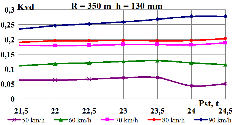
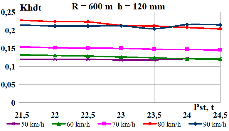
As one can
see from Fig. 10 (a, b),
in general, with loading increase from the car axle on the rails the
vertical dynamics coefficients increase in the whole range of
speeds. The
 indicators do not exceed the permissible norm both in the curve of
m and in the curve of
indicators do not exceed the permissible norm both in the curve of
m and in the curve of
 m and correspond to the excellent level of assessment
 [8].
[8].
a
b

c
d


e
f
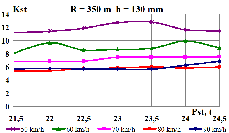
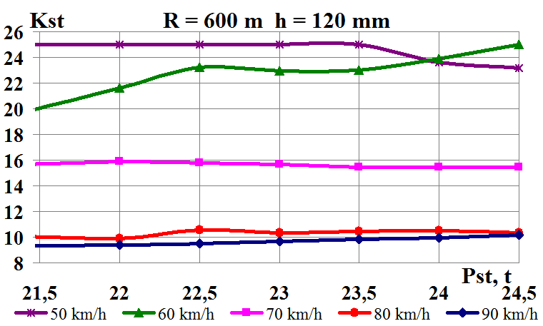
Fig.
10. Dependencde
graphs on the axle loading of the car on rails when moving in the
corresponding curve:
а,
b
– coefficients of vertical dynamics; c,
d
– coefficients of horizontal dynamics;
e,
f
– derailment stability coefficient
Fig. 10 (c,
d), presents the coefficients of
horizontal dynamics
 when moving in curves with a radius
m
and 600 m, correspondingly. From these figures, one can see that
with loading increase from the car axle on the rails, the
coefficients of horizontal dynamics
slightly change and remain in the curves of
and
m at the excellent level of assessment
when moving in curves with a radius
m
and 600 m, correspondingly. From these figures, one can see that
with loading increase from the car axle on the rails, the
coefficients of horizontal dynamics
slightly change and remain in the curves of
and
m at the excellent level of assessment
 [8].
[8].
The
derailment stability coefficients in the curves of
and
m
(Fig. 10, d, e)
have little dependence on the loading increase from the car axle on
the rails and in both cases do not exceed the minimum permissible
value
 .
On the average the value
.
On the average the value
 in the curves
m
is 52.2% lower than the corresponding values in the curve
m. From the obtained results, it follows that in case of increase of
loading from the car axle on the rails, the movement speed has a
significant influence on the car stability in the curved track
sections.
in the curves
m
is 52.2% lower than the corresponding values in the curve
m. From the obtained results, it follows that in case of increase of
loading from the car axle on the rails, the movement speed has a
significant influence on the car stability in the curved track
sections.
Fig. 11 shows
the coefficients of vertical
 and horizontal
 dynamics of the track according to the forces of interaction of the
wheels and rails, as well as the displacement stability coefficient
dynamics of the track according to the forces of interaction of the
wheels and rails, as well as the displacement stability coefficient
 of
the track panel when moving in the corresponding curved track
sections.
of
the track panel when moving in the corresponding curved track
sections.
a
b

c
d
e
f
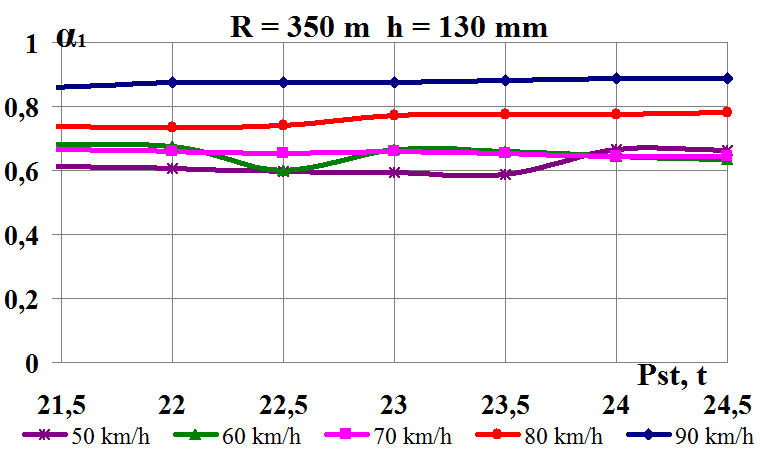

Fig.
11. Graphs of dependence on the axle loading of car
on the rails
when moving in the corresponding curve:
a,
b –
coefficient
of vertical dynamics of the track for the forces of interaction of
wheels and rails;
c,
d
–
coefficient
of horizontal dynamics of the track for the forces of interaction of
wheels and rails;
e,
f
–
displacement
stability coefficient of the track panel
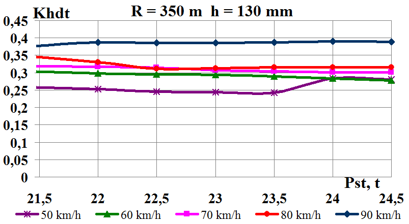
The
permissible value of the coefficient of vertical dynamics of the
track
is calculated according to the permissible dynamic load per unit
length on the railway track from the group of the bogie axles of 168
kN/m and is
 for this type of rolling stock [7]. The coefficient of vertical
dynamics of the track
(Fig. 11, a, b)
does not exceed the permissible value in the curves with radius of
and 600 m.
for this type of rolling stock [7]. The coefficient of vertical
dynamics of the track
(Fig. 11, a, b)
does not exceed the permissible value in the curves with radius of
and 600 m.
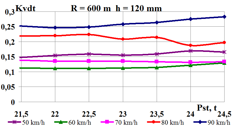
The
coefficient of horizontal dynamics of the track
(Fig. 11, e, f),
which is considered the safety criterion against the track panel
displacement, does not exceed the permissible value
 in the curves with radius of
and 600 m. Only at the speed of 90 km/h in the curve of
m
on average has a value of 0.39 and approaches the maximum
permissible value.
in the curves with radius of
and 600 m. Only at the speed of 90 km/h in the curve of
m
on average has a value of 0.39 and approaches the maximum
permissible value.
The value of
the stability coefficient of the track panel
(Fig. 11, c, d)
in the track with broken stone ballast is 0.6-0.9, which is less
than the permissible value. Therefore for the track with broken
stone ballast at normal movement speeds ( km/h)
one should take
km/h)
one should take
 [5, 7].
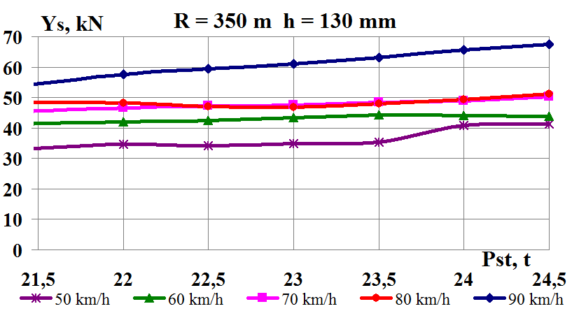
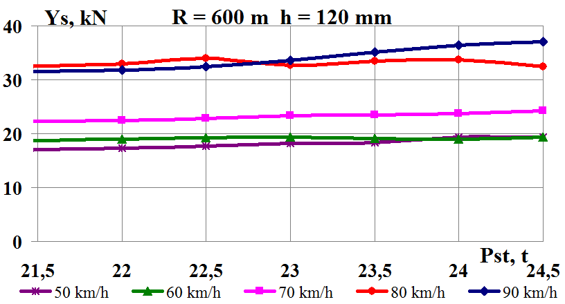
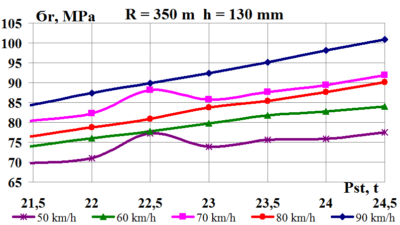
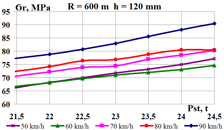
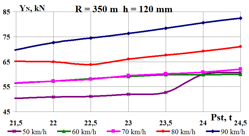
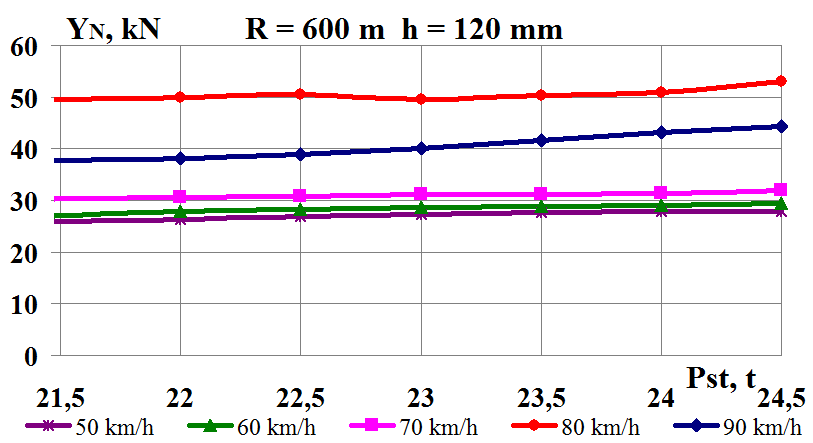
Fig. 12 shows
the speed influence on the interaction indicators of track and
rolling stock in the curves of
and
m, correspondingly – the side force acting from the track on the
wheel, the edge stress at the rail base, the wear factor of the side
edge of the wheel tread.
a
b
c
d
e
f
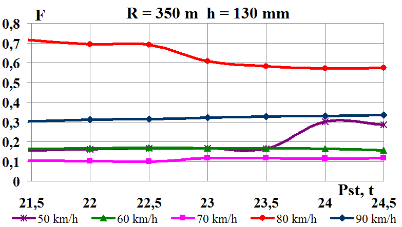
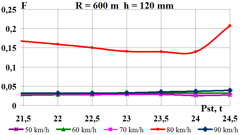
Fig. 12. Graphs of
dependence on the axle loading of the car on rails when moving in
the corresponding curve:
a,
b – side force
acting from the track side on the wheel; c,
d – edge stress at
the rail base;
e, f
– the wear factor
of the side edge of the wheel tread
The side
forces acting from the track on the wheel (horizontal forces)
 (Fig. 12, a, b)
increase and, in comparison with the permissible values of 100 kN,
have no excess. The values
in the curve of
are on the average 46.1 % higher than the corresponding values in
the curve of
(Fig. 12, a, b)
increase and, in comparison with the permissible values of 100 kN,
have no excess. The values
in the curve of
are on the average 46.1 % higher than the corresponding values in
the curve of
m.
The dynamic
influence of rolling stock on the track increases with increasing
the speeds of train movement, and, as a result, the stresses at the
rail base edges increase (Fig. 12, c,
d). The maximum stresses occurring at
the edges of the rail bases are used as a criterion for establishing
the permissible speeds and should not exceed 215 MPa before the
passage of the normative tonnage and 165 MPa after the passage of
the normative tonnage for the track with non-heat treated rails P65.
According to
the results of calculations, the edge stresses increase with
increasing the movement speed and do not exceed the permissible
values for both types of rails [5, 7].
As the
movement speed increases, for example at the speed of 80 km/h, the
wear factor of the side edge of the wheel tread F
increases significantly (Fig. 12, e,
f) and in the curve of
m it 74.86% exceeds the corresponding value at
m. In turn, F
increase at the speed of 80 km/h in the curve
m is 66.2% as compared with other speed intervals. The same
indicator in the curve
m is 80.5%.
The wear
factor of the side edge of the wheel tread F
is determined as a characteristic equal to the product of the
guiding force
 on the angle of hunting (climbing)
 of the wheel on the rail. Fig. 13 shows the speed influence on the
interaction indicators of rolling stock and track in the curves of
m
and
m,
correspondingly, guiding force acting on the wheel from the track
side on the wheel and the wheel set hunting.
of the wheel on the rail. Fig. 13 shows the speed influence on the
interaction indicators of rolling stock and track in the curves of
m
and
m,
correspondingly, guiding force acting on the wheel from the track
side on the wheel and the wheel set hunting.
а
b
c
d
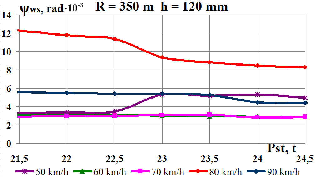

Fig.
13. Graphs of dependence on the axle loading of the car on the rails
in the corresponding curve:
a,
b –
guiding force acting from the track side on the wheel; c,
d
– wheel set hunting
Guiding
forces acting on the wheel
from the track (Fig. 13, a,
b),
significantly increase in the curve of
m with increasing the movement speed. The values
in
the curve of
m on the average are 43.6% more than the corresponding values in the
curve of
m.
The results
of calculations show (Fig. 13, c,
d)
that the hunting angle of the wheel set
at
the speed of 80 km/h in the curves of the small and middle radius is
significantly differ from the other range of the investigated
speeds. The
values
in the curve of
m on average exceed the corresponding value in the curve of
m by
64.9%.
The need to
limit the speed of cars on the bogies of the model 18-100 is due to
the loss of movement stability, when the dynamic transverse
oscillations of the hunting of the car parts stop damping, becoming
steady (self-oscillations). The wheel sets after the loss of
movement stability continuously oscillate within the rail gap, while
the amplitude of self-oscillations may vary within the rail gap, but
no oscillation damping is observed. The side frames of the bogie are
subject to auto-oscillations of the hunting, since the dynamic
movements of the wheel sets are violated predominantly in the
antiphase. The car body in turn, starts hunting because of antiphase
dynamic displacements of the bogies.
As it is
known, the safe train movement speed, which include the cars on the
serial bogies of the model 18-100, is determined not by the design
speed . .,
but by the critical one
.,
but by the critical one
 ,
which is unstable. The critical speed
varies
according to the following factors [10]:
,
which is unstable. The critical speed
varies
according to the following factors [10]:
– the
stiffness of the elastic connection between the sidewalls and the
wheel sets;
– the car
weight – the critical speed of empty cars is lower than that of
the loaded ones;
– gravity
center of the car – with the increase in the gravity center the
critical speed is reduced.
In addition,
the critical speed
changes during operation depending on the wear of undercarriages,
primarily the wheel rims, and the track plan - when passing the
curved track sections, the critical speed is higher compared to the
value in the straight track sections. At speeds exceeding the
critical one, the car loses movement stability. As a result, there
are self-oscillations of the lateral swaying of the wheel sets, the
bogies and body hunting. There is increase in the horizontal
transverse accelerations and frame forces, which wor-sens the
stability coefficient against derailment (Fig. 10, e,
f).
Thus, the movement speed
limitation in the curves of small and medium radius, established by
the norms, should be observed. It caused by a sharp decrease in the
stability coefficient against derailment and increase in the wear
factor of the lateral edge of the wheel tread.
Originality
and practical value
Originality of the work lies in
the study of the influence of increasing the axle loading in gondola
cars on their dynamic parameters and interaction indicators of the
tracks and rolling stock in order to solve the problem of predicting
the rolling stock dynamics and includes the results of theoretical
studies taking into account the movement speed in the curved track
sections of the small and medium radius.
The obtained results have a
practical orientation. During the theoretical studies and after the
simulation, taking into account the oscillation processes of the
freight car and cargo with increase in the gondola axle loading,
dependences of the main dynamic parameters taking into account the
movement speed are obtained. Application of the results will
increase the traffic safety of freight cars and will improve the
technical and economic performance of railway transport.
Conclusions
The article presents analysis of
theoretical studies of dynamic qualities of rolling stock on the
example of gondola cars, calculations are made using the package of
applied programs.
Based on the theoretical study,
the following conclusions can be made:
– the
movement speed limitation in the curves of the small and medium
radius is caused by a decrease in the level of the derailment
stability coefficient and increase in the wear factor of the side
edges of the wheel tread and should not exceed the values determined
by the norms;
– the
calculations have shown the need to limit the movement speed in the
curves of medium radius to 70 km/h, due to the fact that the average
weighted speed of trains of 80 km/h is critical for the gondolas on
the bogies of the model 18-100, which leads to the loss of stability
and increase in the wear factor of the side edge of the wheel tread;
– axle
loading increase will increase failure rate of the rails due to
defects of contact-fatigue nature, deterioration of the track
condition, artificial structures, and the roadbed, which in turn
will cause the movement speed limitation of passenger and freight
trains, as well as more intense failure of elements of the track
superstructure and increase in the annual operating costs.
LIST OF REFERENCE LINKS
Автоматизированная
система дозированной
погрузки щебня
в вагоны
[Electronic resource].
– Available
at: https://clck.ru/F7bWE
– Title from the screen.
– Accessed :
30.01.2019.
Аппаратно-программный
комплекс контроля
загрузки вагонов
«АРСИС.Сканер»
[Electronic resource]
// ООО
«Малленом Системс».
– Available at:
http://www.mallenom.ru/Docs/ARSCIS.Scanner.pdf
– Title from the screen.
– Accessed :
30.01.2019.
Вагонний
парк ПАТ «Укрзалізниця» та взаємодія
з приватними власниками рухомого
складу / Департамент розвитку і технічної
політики (ЦТЕХ) ; кер. ПАТ «Укрзалізниця».
– Харків, 2017. – 11 с.
Вагонные
весы [Electronic
resource] //
Точное Определение Массы
(ТОМ). – Available at:
http://tom.odessa.ua/index.php?p=vagon
– Title from
the screen.
– Accessed :
28.01.2019.
Даніленко,
Е. І. Залізнична колія : підруч. для вищ.
навч. закл. : у 2 т. / Е. І. Даніленко. –
Київ : Інпрес, 2010. – Т. 2. – 456 с.
Данович, В.
Д. Математическая модель пространственных
колебаний сцепа пяти вагонов, движущихся
по прямолинейному участку пути / В. Д.
Данович, А. А. Малышева // Транспорт.
Нагруженность и прочность подвижного
состава : сб. науч. тр.
/ Днепропетр. гос. техн.
ун-т ж.-д. трансп. – Днепропетровск,
1998. – С. 62–69.
ДСТУ
7571:2014. Рухомий склад залізниць. Норми
допустимого впливу на залізничну колію
1520 мм. – Введ. 2014–02–12. – Київ : УкрНДНЦ,
2014. – 33 с.
ДСТУ ГОСТ
33211:2017. Вагони вантажні. Вимоги до
міцності та динамічних якостей (ГОСТ
33211-2014). – Введ. 2017–07–01. – Київ : УкрНДНЦ,
2017. – 58 с.
Засоби для
механізації розрівнювання насипних
вантажів у напіввагонах / Є. В. Романович,
Г. М. Афанасов, Л. М. Козар, В. В. Бут // Зб.
наук. пр. Укр. держ. акад. залізн. трансп.
– Харків, 2014. – Вип. 148 (1). – С.
116–121.
Лазарян, В.
А. Устойчивость движения рельсовых
экипажей / В. А. Лазарян, Л. А. Длугач, М.
Л. Коротенко. – Киев : Наукова думка,
1972. – 197 с.
Определение
допустимых сил при оценке устойчивости
грузовых вагонов от выжимания в поездах
/ А. А. Швец, К. И. Железнов, А. С. Акулов,
А. Н. Заболотный, Е. В. Чабанюк // Наука
та прогрес транспорту. – 2016. – № 1 (61).
– С. 189–192. doi: 10.15802/stp2016/61045
Правила
перевезення вантажів навалом і насипом
(ст. 37 Статуту) [Electronic
resource] : затв.
Наказом М-ва транспорту та зв’язку
України від 20.08.2001 р. № 542 // Законодавство
України. – 2014. – Available
at:
http://zakon.rada.gov.ua/laws/show/z0795-01
– Title from
the screen.
– Accessed :
28.01.2019.
Правила
перевезення вантажів у вагонах
відкритого типу
(https://zakon.rada.gov.ua/laws/show/457-98-п TARGET="_blank" ст.
32 Статуту)
[Electronic resource]
: затв. Наказом М-ва транспорту та
зв’язку України від 20.08.2001 р. № 542 //
Законодавство України. – 2014. – Available
at:
http://zakon.rada.gov.ua/laws/show/z0796-01 – Title
from the
screen. –
Accessed :
28.01.2019.
Рибкін, В.
В. Проведення випробувань з впливу на
колію та стрілочні переводи рухомого
складу нового покоління з осьовим
навантаженням 25 т на вісь / В. В. Рибкін,
В. Є. Савлук // Зб. наук. пр. Укр. держ.
акад. залізн. трансп. – Харків, 2012. –
Вип. 130. – С. 127–131.
Транспортно-разгрузочное
оборудование [Electronic
resource]
// Предприятие
Днепротяжмаш. – Avai-lable
at:
http://www.dts.dp.ua/ru/factories/dnieprotiazhmash/products/transportno-razghruzochnoie-oborudovaniie
– Title from
the screen.
– Accessed :
28.01.2019.
Швець,
А. О. Вплив поздовжнього та поперечного
зміщення центру ваги вантажу в піввагонах
на їх динамічні показники / А. О. Швець
// Наука та прогрес
транспорту. – 2018. – № 5
(77). – С. 115–128. doi:
10.15802/stp2018/146432
Швець, А. О.
Особливості визначення моментів
інерції кузовів вантажних вагонів /
А. О. Швець // Вісник сертифікації
залізничного транспорту. – 2018. – № 5
(51). – С. 20–34.
Determination
of the issue concerning the lift resistance factor of lightweight
car / A. O.
Shvets, К. I. Zhelieznov, А.
S. Аkulov, О.
M. Zabolotnyi, Ye. V. Chabaniuk // Наука
та прогрес транспорту. –
2015. –
№
6 (60). – С. 134–148. doi:
10.15802/stp2015/57098
Effect of fracture
toughness on vertical split rim failure in railway wheels / T.
Kato, Y. Yamamoto, H. Kato,
S. Dedmon, J. Pilch // Engineering
Fracture Mechanics. – 2017. – Vol. 186. – P. 255–267.
doi:
10.1016/j.engfracmech.2017.09.025
Fatigue
behavior and microstructural characterization of a high strength
steel for welded railway rails / R. Baptista, T. Santos, J.
Marques, M. Guedes, V. Infante // International Journal of Fatigue.
– 2018. – Vol. 117. – P. 1–8.
doi: 10.1016/j.ijfatigue.2018.07.032
Kurhan,
D. Determination of Load for Quasi-static Calculations of Railway
Track Stress-strain State /
D. Kurhan // Acta Technica Jaurinensis. – 2016. – Vol.
9. –
Іss.
1. – Р.
83–96.
doi: 10.14513/actatechjaur.v9.n1.400
Nikas,
D. Evaluation of local strength via microstructural quantification
in a pearlitic rail steel deformed by simultaneous compression and
torsion / D. Nikas, X. Zhang, J. Ahlström // Materials Science and
Engineering: A.
– 2018. – Vol. 737. – P.
341–347. doi: 10.1016/j.msea.2018.09.067
А.
О. Швець1*,
О. О. болотов2*
1*Каф.
«Теоретична та будівельна механіка»,
Дніпровський національний університет
залізничного
транспорту імені академіка
В. Лазаряна, вул. Лазаряна, 2, Дніпро,
Україна, 49010, тел.
+38 (050) 214 14 19,
ел. пошта angela_Shvets@ua.fm, ORCID
0000-0002-8469-3902
2*ГНДЛ ДМРС, Дніпровський
національний університет залізничного
транспорту імені академіка В. Лазаряна,
вул. Лазаряна, 2, Дніпро, Україна,
49010, тел. +38 (097) 977 57 08, ел. пошта bolaks@i.ua,
ORCID 0000-0002-0807-0340
Вплив
навантаження від осі ПІВвагона на його
динамічні ПОКАЗНИКи та залізничну
колію
Мета.
Підвищення максимального навантаження
від осі вагона на рейки під час перевезення
вантажів і збільшення швидкості руху
залізничних екіпажів дозволить посилити
інтеграційні процеси між країнами. Для
гарантування безпечного й надійного
сполучення на залізницях необхідно
вдосконалювати контроль, кількісну
оцінку динамічної завантаженості
рухомого складу, що в процесі його
експлуатації складає актуальну
науково-технічну задачу. Метою цієї
роботи є дослідження впливу збільшення
осьового навантаження в піввагонах, з
урахуванням можливого підвищення
швидкості руху, на їх основні динамічні
показники та показники взаємодії
рухомого складу з колією. Методика.
Дослідження проведене методом
математичного й комп’ютерного
моделювання динамічної завантаженості
піввагона з використанням моделі
просторових коливань зчепу п’яти
вагонів і програмного комплексу,
розробленого в галузевій науково-дослідній
лабораторії динаміки й міцності рухомого
складу (ГНДЛ ДМРС). Вихідні дані для
дослідження: рух піввагона моделі
12-532 з типовими візками 18-100 зі швидкостями
в діапазоні від 50 до 90 км/год в кривих
радіусами 350 і 600 м, із підвищеннями
зовнішньої рейки 130 та 120 мм відповідно.
Результати. У
статті проаналізовано динамічні якості
рухомого складу на прикладі піввагонів;
розрахунки виконано з використанням
пакета прикладних програм з достатньою
для практики точністю. У ході теоретичних
досліджень і моделювання з урахуванням
процесів коливання вантажного вагона
в разі збільшення осьового навантаження
отримано залежності основних динамічних
показників від швидкості руху. Наукова
новизна роботи полягає
в дослідженні впливу збільшення осьового
навантаження в піввагонах з урахуванням
можливого підвищення швидкості руху
на їх динамічну завантаженість із метою
вирішення задачі прогнозування динаміки
рухомого складу. Уперше отримано
результати теоретичних досліджень з
урахуванням швидкості руху в кривих
ділянках колії малого та середнього
радіуса. Практична
значимість. Застосування
цих результатів сприятиме підвищенню
безпеки руху вантажних вагонів і
дозволить поліпшити техніко-економічні
показники роботи залізничного транспорту.
Ключові
слова: вантаж; піввагони; динамічні
показники; криві ділянки колії; осьове
навантаження; показники взаємодії;
рухомий склад і колія; центр ваги;
швидкість руху
А.
А. Швец1*,
А. А. болотов2*
1*Каф.
«Теоретическая и строительная механика»,
Днипровский национальный
университет железнодорожного
транспорта
имени академика В. Лазаряна, ул. Лазаряна,
2, Днипро, Украина, 49010, тел. +38 (050) 214 14 19,
эл. почта angela_Shvets@ua.fm, ORCID
0000-0002-8469-3902
2*ОНИЛ
ДППС, Днипровский
национальный университет железнодорожного
транспорта имени академика
В. Лазаряна,
ул. Лазаряна, 2, Днипро, Украина, 49010, тел.
+38 (097) 977 57 08, эл. почта bolaks@i.ua,
ORCID
0000-0002-0807-0340
ВЛИЯНИЕ
НАГРУЗКИ ОТ ОСИ полувагона НА ЕГО
динамические показатели И железнодорожный
путь
Цель.
Повышение максимальной
нагрузки от оси вагона на рельсы при
перевозке грузов и увеличение скорости
движения железнодорожных экипажей
позволит усилить интеграционные
процессы между странами. Для обеспечения
безопасного и надежного сообщения на
железных дорогах
необходимо
совершенствовать контроль, количественную
оценку динамической загруженности
подвижного состава, что в процессе его
эксплуатации составляет актуальную
научно-техническую задачу. Целью данной
работы является исследование влияния
увеличения осевой нагрузки в полувагонах,
с учетом возможного повышения скорости
движения, на их основные динамические
показатели и показатели взаимодействия
подвижного состава с колеей. Методика.
Исследование проведено методом
математического и компьютерного
моделирования динамической загруженности
полувагона с использованием модели
пространственных колебаний сцепа пяти
вагонов и программного комплекса,
разработанного в отраслевой
научно-исследовательской лаборатории
динамики и прочности подвижного состава
(ОНИЛ ДППС). Исходные данные исследования:
движение полувагона модели 12-532 с
типичными тележками 18-100 со скоростями
в диапазоне от 50 до 90 км/ч в кривых
радиусами 350 и 600 м, с повышениями
наружного рельса 130 и 120 мм соответственно.
Результаты.
В статье проанализированы динамические
качества подвижного состава на примере
полувагонов; расчеты выполнены с
использованием пакета прикладных
программ с достаточной для практики
точностью. В ходе теоретических
исследований и моделирования с учетом
процессов колебания грузового вагона
при увеличении осевой нагрузки получены
зависимости основных динамических
показателей от скорости движения.
Научная новизна
состоит в исследовании влияния увеличения
осевой нагрузки в полувагонах с
учетом возможного повышения скорости
движения на их динамическую нагрузку
с целью решения задачи прогнозирования
динамики подвижного состава. Впервые
представлены результаты теоретических
исследований с учетом скорости
движения по кривым участкам пути малого
и среднего радиуса. Практическая
значимость. Применение
полученных результатов будет
способствовать повышению безопасности
движения грузовых вагонов и позволит
улучшить технико-экономические
показатели работы железнодорожного
транспорта.
Ключевые
слова: груз; полувагоны; динамические
показатели; кривые участки пути; осевая
нагрузка; показатели взаимодействия;
подвижной состав и колея; центр тяжести;
скорость движения
REFERENCES
Avtomatizirovannaya
sistema dozirovannoy pogruzki shchebnya v vagony.
Retrieved from
https://clck.ru/F7bWE (in Russian)
Apparatno-programmnyy
kompleks kontrolya zagruzki vagonov «ARSIS.Skaner».
OOO «Mallenom Sistems».
Retrieved from
http://www.mallenom.ru/Docs/ARSCIS.Scanner.pdf
(in Russian)
Vagonnyj
park PAT «Ukrzaliznycja» ta vzajemodija z pryvatnymy vlasnykamy
ruhomogo skladu. (2017). Kharkiv: Department of Development and
Technical Policy; manager PJSC «Ukrzaliznytsya». (in Ukrainian)
Vagonnye
vesy. Tochnoe Opredelenie Massy (TOM).
Retrieved from
http://tom.odessa.ua/index.php?p=vagon
(in Russian)
Danilenko,
E. I. (2010). Zaliznychna
koliia:
pidruchnyk
dlia
vyshchykh
navchalnykh
zakladiv.
(Vol. 1-2). Kyiv: Inpres. (in
Ukrainian)
Danovich,
V. D., & Malysheva, A. A. (1998). Mathematical Model of Spatial
Oscillations of the Coupling of Five Cars Moving Along a
Rectilinear Section of the Track.
Transport. Stress Loading and
Durability of a Rolling Stock (рр.
62-69).
Dnepropetrovsk.
(in Russian)
Rukhomyj
sklad zaliznycj. Normy dopustymogho vplyvu na zaliznychnu koliju
1520 mm. 33 DSTU 7571:2014 (2014). (in
Ukrainian)
Vahony
vantazhni. Vymohy do mitsnosti ta dynamichnykh yakostei, 58 DSTU
33211:2017 (2017). (in Ukrai-nian)
Romanovych,
Y. V., Afanasov, H. M., Kozar, L. M., &
But, V. V. (2014).
Zasoby dlia mekhanizatsii rozrivniuvannia
nasypnykh vantazhiv u napivvahonakh. Collected
Scientific Works of Ukrainian State University of Railway
Transport,
148(1),
116-121. (in Ukrainian)
Lazaryan,
V. A., Dlugach, L. A., & Korotenko, M. L. (1972). Ustoychivost
dvizheniya relsovykh ekipazhey. Kiev:
Naukova dumka. (in Russian)
Shvets,
A. O., Zhelieznov, K. I., Akulov, A. S., Zabolotnyi, O. M., &
Chabaniuk, E. V. (2016). Determination the permissible forces in
assessing the lift resistant factor of freight cars in trains.
Science and Transport Progress, 1(61),
180-192. doi: 10.15802/stp2016/61045
(in Russian)
Pravyla
perevezennia vantazhiv navalom i nasypom (2014). Retrieved from
http://zakon.rada.gov.ua/laws/show/z0795-01
(in Ukrainian)
Pravyla
perevezennia vantazhiv u vahonakh vidkrytoho typu (2014). Retrieved
from http://zakon.rada.gov.ua/laws/show/z0796-01 (in
Ukrainian)
Rybkin,
V. V., & Savluk, V. Y. (2012). Provedennia vyprobuvan z vplyvu
na koliiu ta strilochni perevody rukhomoho skladu novoho pokolinnia
z osovym navantazhenniam 25 t na vis. Collected
Scientific Works of Ukrainian State University of Railway
Transport, 130, 127-131.
(in Ukrainian)
Transportno-razgruzochnoe
oborudovanie. Predpriyatie
Dneprotyazhmash. Retrieved from
http://www.dts.dp.ua/ru/factories/dnieprotiazhmash/products/transportno-razghruzochnoie-oborudovaniie
(in Russian)
Shvets,
A. O. (2018). Influence of the longitudinal and transverse
displacement of the center of gravity of the load in gondola cars
on their dynamic indicators. Science
and Transport Progress, 5(77),
115-128.
doi:
10.15802/stp2018/146432
(in Ukrainian)
Shvets,
A. O. (2018). Specifics of Determining the Moments of Inertia a
Freight Wagons Bodies.
Visnyk sertyfikatsii zaliznychnoho
transportu,
5(51), 20-34.
(in Ukrainian)
Shvets,
A. O., Zhelieznov, К. I., Аkulov, А. S., Zabolotnyi, О. M., &
Chabaniuk, Y. V. (2015). Determination of the issue concerning the
lift resistance factor of lightweight car. Science
and Transport Progress, 6(60),
134-148. doi: 10.15802/stp2015/57098 (in
English)
Kato,
T., Yamamoto, Y., Kato, H., Dedmon, S., & Pilch, J. (2017).
Effect of fracture toughness on vertical split rim failure in
railway wheels. Engineering Fracture
Mechanics, 186, 255-267.
doi: 10.1016/j.engfracmech.2017.09.025 (in
English)
Baptista,
R., Santos, T., Marques, J., Guedes, M., & Infante, V. (2018).
Fatigue behavior and microstructural characterization of a high
strength steel for welded railway rails. International
Journal of Fatigue, 117, 1-8.
doi: 10.1016/j.ijfatigue.2018.07.032 (in
English)
Kurhan,
D. (2016). Determination of Load for Quasi-static Calculations of
Railway Track Stress-strain State. Acta
Technica Jaurinensis, 9(1), 83-96.
doi: 10.14513/actatechjaur.v9.n1.400
(in English)
Nikas,
D., Zhang, X., & Ahlström, J. (2018). Evaluation of local
strength via microstructural quantification in a pearlitic rail
steel deformed by simultaneous compression and torsion.
Materials Science and Engineering: A, 737,
341-347. doi: 10.1016/j.msea.2018.09.067 (in
English)
Received:
Sep. 10, 2018
Accepted:
Jan. 18,
2019