ISSN
2307–3489 (Print), ІSSN
2307–6666
(Online)
Наука
та прогрес транспорту. Вісник
Дніпропетровського
національного університету залізничного
транспорту, 2018, № 4 (76)
рухомий
склад залізниць і тяга поїздів
UDC
629.463.027.23-027.45
O.
G. REIDEMEISTER1,
O. А. SHYKUNOV2*
1Dep.
«Cars and Car Facilities», Dnipropetrovsk National University named
after Academician V. Lazaryan, Lazaryan St., 2, Dnipro, Ukraine,
49010, tel. +38 (056) 373 15 04,
e-mail reidemeister.a@gmail.com,
ORCID 0000-0001-7490-7180
2*Dep. «Cars and Car
Facilities», Dnipropetrovsk National University named after
Academician V. Lazaryan, Lazaryan St., 2, Dnipro, Ukraine, 49010,
tel. +38 (056) 373 15 04,
e-mail tri_s@ua.fm, ORCID
0000-0002-8256-2634
SENSITIVITY
OF STRESSES TO THE FORCES ACTING ON THE
CAST
PARTS
OF FREIGHT-CAR
BOGIE
Purpose. To
determine the effect of the force components acting in the axle box
and the central spring suspension on the stresses occurring in the
side frame of the three-piece bogie. Methodology. To assess
the effect of the forces acting on the side frame on the stresses in
it, we developed a finite element model of the side frame. After
that, we carried out an assessment of its stress-strain state under
loading conditions corresponding to the І and ІІІ design modes.
According to the results obtained, we determined the stress
concentration points in the construction, which are selected as check
ones for further studies. Also, as checkpoints we took the points
corresponding to the sensor locations when estimating the stresses in
the side frame during the tests. At the next stage, we applied unit
loads in sequence at the interaction points of the side frame with
the boxes and the central spring group. To obtain a more accurate
result, the unit forces were balanced by the corresponding forces and
moments of inertia. With each loading variant, tensors of stresses
arising from the action of unit loads were obtained at checkpoints.
On the basis of the stress tensors obtained, we determined the
corresponding equivalent stresses – the sensitivity coefficients.
Findings. The paper determines the stress sensitivity
coefficients in the three-piece bogie side frame to external loads
acting on the side frame from the side of axle box and central spring
group. Based on the results of the assessment of the coefficients
obtained, we determined the forces having the greatest influence on
individual sections of the side frame. We estimated the possibility
of using the obtained results in optimizing the parameters of the
bogie spring suspension to increase the strength and durability of
the side frame. Originality. For the first time, the effect of
individual components of the forces acting on the side frame on the
stresses in it has been estimated. Practical value. The
obtained result can be used in the design and optimization of
three-piece bogies, to improve the side frame durability. The stress
tensors obtained can be used to estimate the effect of complex
loading on the side frame strength and durability.
Key words:
strength; side frame; three-piece bogie; durability; freight car
Introduction
The
absence in the three-piece bogies of freight cars of devices
preventing from falling onto the track its main supporting elements
such as the bolster and the side frame sharply raise the reliability
requirements imposed on these elements. However, a fairly large
part of the freight train derailment at the current moment is caused
precisely by defects in the cast parts of the bogies, namely, the
side frame fractures.
The
railway enterprises have been facing the problem of mass fracture of
side frames since 2006 [3, 5, 16] and two main directions can be
identified as the main possible causes.
The
first one is low
quality of casting. Work
in this direction revealed two possible causes – hidden defects in
casting [6] and non-compliance with the established steel viscosity
requirements KCV (-60°C) [2]. To solve these problems, the
works are in progress to improve the casting technology –
regulating the metal cooling by updating the moulding flasks or the
design of the side frame itself. Besides, monitoring more strictly
the quality of metal and casting methods by destructive and
non-destructive controls.
The
second possible cause of mass fractures is structural. In 2001,
there was a transition from the I-section of the arch bar on the
supra-box area to the box-like section [14]. It was suggested that
the I-section of the side frame extension acted as an
elastically deforming quencher of torque, which occurs during
critical loosening of side frames relative to each other and the
corresponding angular displacements of the set of wheels in the
pedestal jaw opening. In other words, the I-section design was less
rigid in the horizontal plane and had a slightly loaded position –
the I-section pedestal, which had a compensating effect of the
bending moments of the set of wheels, and in abnormal operation
modes, all defects in the side frame operation were visible. The
solution to this problem is related to the development of methods
for strengthening the side frame structure on the basis of
calculations and tests to determine its strength [7,
13,
15, 17, 23],
reliability, as well as the dynamic characteristics of the car as a
whole [4, 8,
9, 16,
19, 21, 22].
Possible
solutions are attempts to create welded structures of side frames
[1, 11]. This solution, although it will eliminate the problems of
casting, however raises many questions related to the reliability of
welded joints.
To
increase the reliability of the bogie cast parts, it is also
possible to consider the possibility, at the design stage, of the
influence of the spring suspension parameters on the stresses
arising in the parts.
Purpose
To
determine the effect of the force components acting in the axle box
and the central spring suspension on the stresses occurring in the
side frame of the three-piece bogie.
Methodology
The
sensitivity of the indicator
 to the value
 (
( – index that separates the considered quantity from the set of
values
– index that separates the considered quantity from the set of
values
 ,
which
,
which depends
on) means the ratio of the change in the indicator
depends
on) means the ratio of the change in the indicator
 to the change
in the argument
to the change
in the argument
 ,
,
 (1)
(1)
In
the case of a linear dependence of the exponent on all arguments,
this definition is unambiguous in the sense that the sensitivity
value
 does not depend on the fact at which values of the arguments the
indicator
was calculated, as well as on the selected increment
.
In the general case it is necessary somehow to characterize the
totality of the values
in a compact form. It
is common to use the Morris method for this purpose [20], which
consists in the fact that the sensitivity values are calculated at
random points in the domain of definition with specially chosen
increments of arguments (to reduce the amount of calculations),
and then the mathematical expectation
does not depend on the fact at which values of the arguments the
indicator
was calculated, as well as on the selected increment
.
In the general case it is necessary somehow to characterize the
totality of the values
in a compact form. It
is common to use the Morris method for this purpose [20], which
consists in the fact that the sensitivity values are calculated at
random points in the domain of definition with specially chosen
increments of arguments (to reduce the amount of calculations),
and then the mathematical expectation
 and the
mean-square
deviation of the sensitivities
and the
mean-square
deviation of the sensitivities
 are
analysed. Fulfilment of condition
are
analysed. Fulfilment of condition
 (2)
(2)
indicates
a substantially nonlinear character of the dependence.
Since
the dependence of the stress tensor components on the loads is
linear, and the change in the parameters of the running parts causes
a relatively small change in the loads, the nonlinearities (in
determining the equivalent stresses and the number of cycles before
the appearance of fracture) can hardly be regarded as essential,
which eliminates the need to apply more sophisticated methods of
sensitivity analysis such as Sobol's
indices [18].
Stresses
that arise in the bogie side frame under the action of a static load
are shown in Figure 1. The heavily loaded areas near the lower
corner of the central spring opening, on the lower side frame member
and at the point R55 of the pedestal jaw opening are clearly
visible. The stress levels in these places for various combinations
of loads are given in Table 1 and approach the maximum permissible
values for 20GL steel. The І calculation mode corresponds to the
loading variants a and b, and III to c...f. Also, the stress
concentration is noticeable in the corners of the process window
(101 MPa) and the upper corners of the central spring opening (114
MPa).
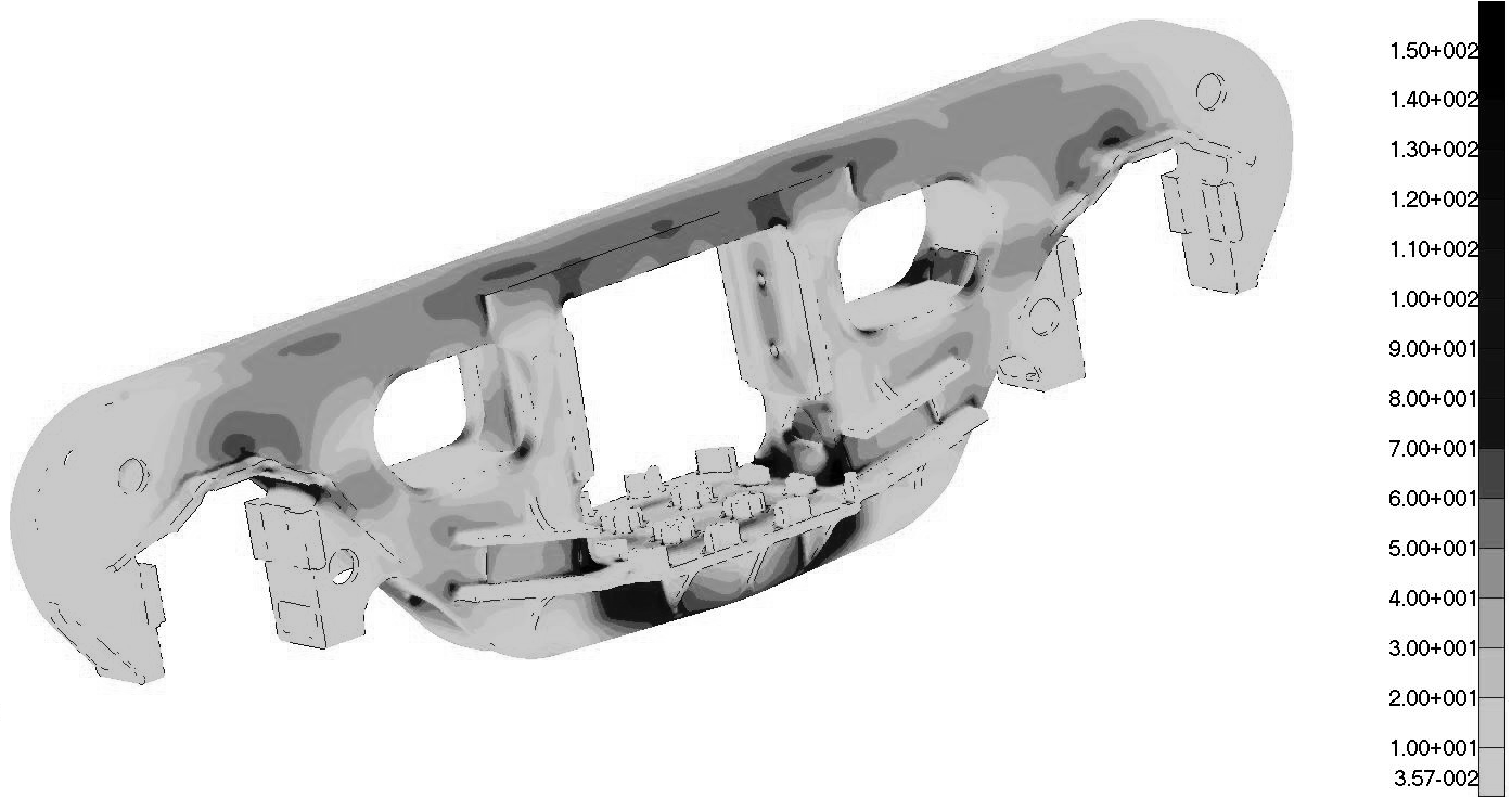
Fig.
1. Stress distribution
in side frame model
for the
III-design mode, MPa.
The
stress concentration at these points is expected from the point of
view of the geometry of the model. Also these points are checkpoints
according to [12].
Table
1
Maximum
stresses in the bogie side frame, MPa
|
Loading
variant
|
Place
of occurrence
|
Permissible
values
|
Estimated
value
|
Checkpoints
|
|
a
|
Lower
corners of the central spring opening
|
250
|
240
|
6,
7, 27
|
|
b
|
Vertical
pedestal roof
|
250
|
235
|
14,
15,
|
|
c
|
Lower
corners of the central spring opening
|
140
|
132
|
6,
7, 27
|
|
d
|
Vertical
pedestal roof
|
140
|
137
|
14,
15,
|
|
e
|
Vertical
pedestal roof
|
140
|
139
|
14,
15,
|
|
f
|
Lower
corners of the central spring opening
|
140
|
131
|
6,
7, 27
|
Taking
into account the obtained results, the points shown in Figure 2 were
chosen to estimate the stressed state of the side frame. Their total
number is 43, they are located in the middle of the lower side frame
member (1-5, 18, 19, 25), in the upper (8, 9) and the lower (6, 7,
26, 27) corners of the central opening for spring suspension, in the
opening between the diagonal tension member and the column (10-13),
in the inner corner of the pedestal opening (14, 15), in the middle
(20-24) and the cantilever part (16, 17) of the arch bar. The points
located symmetrically are not shown in Fig. 2. And they are assigned
with the numbers 4'... 27'.
The
side frame perceives the forces from the central spring suspension
and the axle box. To assess the effect of these forces on the
stresses arising in the side frame, we sequentially determined the
stresses from unit forces acting in three directions at the
appropriate places. To balance the action of unit forces on the side
frame, we applied inertia forces and a moment of inertia
corresponding to the acting forces. The points of application of
unit forces and the direction of the local coordinate axes are shown
in Figure 3

Fig.
2. Checkpoints
.
Fig.
3. Points of application of unit forces
Findings
As
a result of the calculation, we obtained the tensors of stresses
arising from the action of unit loads at the side frame checkpoints.
On the basis of the obtained stress components, the corresponding
equivalent stresses arising from the action of unit loads, the
sensitivity coefficients, were calculated. The intensity of the
effect of unit forces on the stresses at the points of the finite
element model is shown in Fig. 4.
In
Figure 4, the intensity of the shading of individual cells
characterizes the degree of the force effect on equivalent stresses
at the point of the model.
Analyzing
the results of the calculation, we can conclude that the points 6,
8, 9 and symmetrical 6', 8' and 9 '- the lower and upper corners of
the central spring opening – are the most sensitive to changes in
the external load, up to 1.204 MPa/kN. Point 26, strengthening rib
in the lower member, is sensitive to the vertical load from the
sub-key spring – 1.054 MPa/kN.
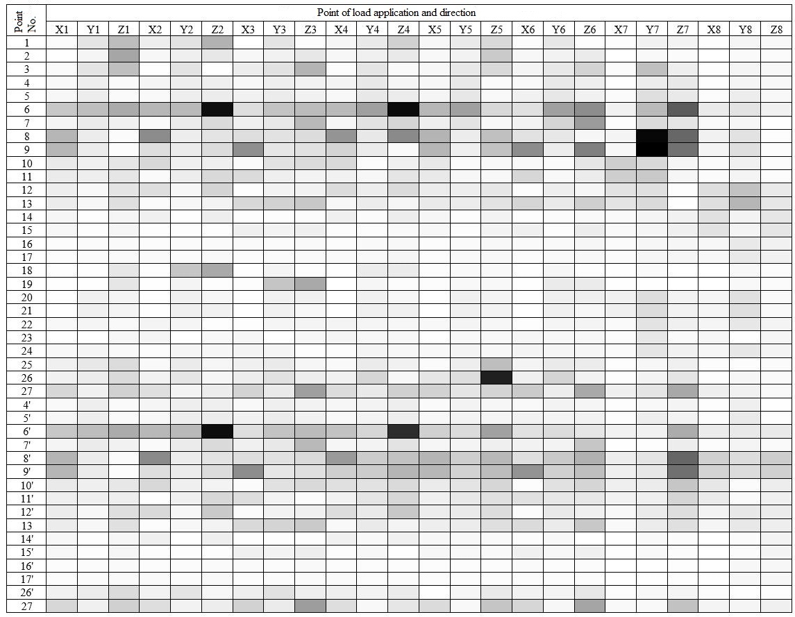
Fig.4.
The intensity of the effect of unit forces on the stresses at the finite element model points
The
points located on the lower member (p. 1 – 3, 18, 19, 25), the
lower corner of the central spring opening (p. 6, 7, 27) are
sensitive to vertical loads acting on the central opening roof, the
sensitivity factor is 0.411 MPa/kN and 1.154 MPa/kN respectively,
and points 6, 7, 27 are also sensitive to vertical loads from the
friction key – up to 0.772 MPa/kN. The transition from the lower
member to the diagonal tension member (p. 4, 5) is almost equally
sensitive to all loading variants except the longitudinal forces in
the pedestal opening and from the action of the friction keys – up
to 0.156 MPa/kN. The upper corner of the central spring opening (p.
8, 9) is sensitive to vertical and transverse loads from the action
of the friction key – up to 1.204 MPa/kN. The
arch bar
in the
middle part
(p. 20-24) is
more sensitive
to the
transverse loads
acting from
the vibration
dampers and
in the
axle box
– up to
0.166 MPa/kN.
For points located in the process window
area (p. 10 – 13) it is quite difficult to determine a specific
group of forces that exert significant influence, since this area
experiences a complex loading – up to 0.348 MPa/kN.
The
inner corner of the pedestal opening (p. 14, 15) is mostly
influenced by longitudinal and vertical forces from the nearest
pedestal opening – up to 0.143 MPa/kN. The arch bar in the
pedestal opening area (p. 16, 17) is
mostly influenced by the forces in the places of vertical and
transverse axle box intersections as well – up to 0.109 MPa/kN,
the influence of the remaining loads is less approximately twofold.
Thus,
to reduce, for example, the stresses in the lower corners of the
pedestal opening (p. 6, 7, 27) by 5% (6.95 MPa, III design mode), it
is necessary to reduce the vertical load on the central spring
opening by 19.64 kN (average sensitivity coefficient is 0.35
MPa/kN). To reduce
stresses in
the inner
corner of
the pedestal
opening (p.
14, 15) by 5%,
it is
necessary to
reduce the
level of
longitudinal or
vertical load
components in
the axle
box by
52 MPa (average
sensitivity
coefficient is
0.132 MPa/kN).
Reducing the load in this range can be
difficult; therefore, along with changes in the parameters of the
spring sets, it is necessary to provide for an increase in the
strength of the structure due to local reinforcement.
In
operation, static forces act on the side frame from the car gross
weight – about 220 kN with an axial load of 23.5 tons per axle and
the dynamic forces arising from the movement of the car can be from
50% to 80% of the static load [10]. Reduction of static loads is not
advisable, since their main component is the load-carrying capacity
of the car. Dynamic loads, the magnitude of which can reach up to
176 kN, can be reduced through the use of rational parameters of
spring suspension and the structure as a whole. At the same time, a
decrease in the dynamic component of the loads acting on the side
frame by only 5% – 8.8 kN, can lead to a decrease in the stress
level in the side frame by 1.37-10.60 MPa. This decrease is not
significant in evaluating the strength of the structure, however, in
assessing its durability, reducing the dynamic load amplitude by 5%
will cause an increase in longevity by 20% (fatigue curve index 4).
Originality
and practical value
For
the first time, the effect of forces acting on the three-piece bogie
side frame on the stress level arising in it has been estimated.
The
obtained sensitivity factors can be used to optimize the parameters
of the freight car bogie for increase of durability of its details.
The
stress tensors obtained can be used to estimate the effect of
complex loading on the side frame strength and durability.
Conclusions
We
determined stress sensitivity coefficients on the certain sections
of the three-piece bogie side frame to external loads acting on the
side frame from the side of the pedestal and spring openings. The
stress tensors obtained can be used to estimate the effect of
complex loading on the side frame strength and durability.
LIST
OF REFERNECE
LINKS
Богатов, А.
А. О повышении служебных характеристик
боковой рамы тележки грузового вагона
/ А. А. Богатов, Р. А. Ильиных // Вестник
ВНИИЖТ. – 2010. – № 6. – С. 42–44.
Волченков,
Н. Стальное литье и методы повышения
качества [Electronic resource]
/ Н. Волченков, В. Моисеенков,
Е. Сургаева // ИИС «Металлоснабжение
и сбыт». – 2011. – Available
at: http://www.metalinfo.ru/ru/news/49443
– Title from
the screen. –
Accessed : 18.07.2018.
Демин, Ю. В.
Улучшение технических характеристик
тележек грузовых вагонов / Ю. В. Демин,
Г. Д. Кочмала // Залізн. трансп. України.
– 1999. – № 3. – С. 26–29.
Динамика
грузовых вагонов с учетом поперечного
смещения тележек / Н. И. Луханин, С. В.
Мямлин,Л. А. Недужая, А. А. Швец // Зб.
наук. пр. Донец. ін-ту залізн. трансп. –
Донецьк, 2012. – № 29. – С. 234–241.
ДСТУ
7598:2014. Вагони вантажні. Загальні вимоги
до розрахунків та проектування нових
і модернізованих вагонів колії 1520 мм
(несамохідних). – Чинний від 2014–01–02.
– Київ : УкрНДНЦ, 2017. – 162 с.
Ишмухамметов,
Ф. Рамы грузовых тележек продолжают
ломаться [Electronic resource]
/ Ф. Ишмухамметов // Коммерсант.ru. –
Available at:
http://www.kommersant.ru/doc/2421946 – Title
from the
screen. – Accessed
: 18.07.2018.
Конькова,
Т. Е. О путях повышения эксплуатационной
надежности стальных литых деталей
тележек грузовых вагонов / Т. Е. Конькова,
В. Б. Беловодский, А. В. Великанов //
Вестник ВНИИЖТ. – 2009. – № 1. – С. 22–26.
Манашкин,
Л. А. Об измерении вертикальных сил в
тележках грузовых вагонов / Л. А.
Манашкин, С. В. Мямлин, Е. А. Письменный
// Вісн. Дніпропетр. нац. ун-ту залізн.
трансп. ім. акад. В. Лазаряна. –
Дніпропетровськ, 2004. –
Вип. 5. – С.
132–135.
Мурадян,
Л. А. Залежність величини зносу пари
тертя «п’ятник–підп’ятник» від
пробігу вантажного вагона / Л. А. Мурадян,
Д. О. Подосьонов, В. Ю. Шапошник // Наука
та прогрес транспорту. – 2017. – № 6
(72). – С. 61–69.
doi:
10.15802/stp2017/118136
Мурадян,
Л. А. К вопросу о планах испытаний
надежности механических систем / Л. А.
Мурадян, В. Ю. Шапошник // Зб. наук. пр.
Укр. держ. ун-ту залізн. трансп. – Харків,
2015. – Вип. 157. – С. 119–128.
Перспективы
создания сварных конструкций несущих
элементов тележки грузового вагона /
О. В. Махненко, Г. Ю. Сапрыкина,
И. В. Мирзов, А. Д. Пустовой //
Автоматическая сварка. – 2014. – № 3.
– С. 36–42.
РД
24.050.37.95. Вагоны грузовые и пассажирские.
Методы испытания на прочность и ходовые
качества. – Москва : ГосНИИВ, 1995. – 101
с.
Рейдемейстер,
А. Г. Способы увеличения прочности
боковых рам трехэлементных тележек /
А. Г. Рейдемейстер, А. А. Шикунов // Наука
та прогрес транспорту. – 2015. – № 5 (59).
– С. 141–149.
doi: 10.15802/stp2015/55351
Савчук, В.
Б. Радиус излома на Совете главных
конструкторов / В. Б. Савчук, Г.
М. Зобов // Техника железных дорог.
– 2013. – № 2 (22). – С. 32–36.
Ушкалов,
В. Ф. Определение состава и уровня сил,
действующих на консольную часть боковой
рамы в процессе эксплуатации грузового
вагона / В. Ф. Ушкалов, Н. В. Безрукавый
// Техническая механика. – 2016. – № 2. –
С. 85–90.
Шупелов,
Н. Анализ изломов боковых рам (2006÷2014
гг.) [Electronic resource] / Н.
Шупелов
// MyShared. – Available at: http://www.myshared.ru/slide/992141
– Title from the screen. – Accessed : 18.07.2018.
A
new lever-type variable friction damper for freight bogies used in
heavy haul railway / Ximing
Xu, Maohai Fu, Zhaoxia Xu, Zhongyi Chen //Journal
of Modern Transportation. – 2016. – Vol. 24. – Iss. 3. – P.
159–165.
doi: 10.1007/s40534-016-0116-4
Global
sensitivity analysis. The primer / A. Saltelli, M. Ratto, T.
Andres, F. Campolongo, J. Cariboni, D. Gatelli, M. Saisana, S.
Tarantola. – Chichester, West Sussex, England : John Wiley &
Sons, 2008. – 292 p.
Mathematical
Modeling of Dynamic Loading of Cassette Bearings for Freight Cars /
S. Myamlin, O. Lunys, L. Neduzha, O. Kyryl’chuk // Тransport
Means : Proc. of 21st Intern. Scientific Conf. (20–22nd
September, 2017). – Kaunas, 2017.
– Р. 973–976.
Morris,
M. D. Factorial sampling plans for preliminary computational
experiments / Max D. Morris // Technometrics. – 1991. – Vol.
33, No. 2. – Р. 161–174.
Prospects
for the Use of Gondola Cars on Bogies of Model ZK1 in the
Organization of Heavy Freight Traffic in the Republic of Kazakhstan
/ S.
Abdullayev, G. Imasheva, N. Tomkurzina, N. Adilova, G. Bakyt //
Mechanics. – 2018. – Vol. 24. – Iss. 1. – P. 32–36. doi:
10.5755/j01.mech.24.1.17710
Reidemeister,
O. H. Method of Constructing the Dynamic Model of Movement of the
Multi-Mass System / O. H.
Reidemeister, V. O. Kalashnyk, O. A. Shykunov //
Наука та
прогрес транспорту.
– 2017. – № 5 (71). – С. 99–106.
doi:
10.15802/stp2017/112921
Shykunov,
O. A. Three-element bogie side frame strength / О.
А. Shykunov // Наука
та прогрес
транспорту. – 2017. – № 1
(67). – С.
183–193.
doi: 10.15802/stp2017/92535
О. Г. РЕЙДЕМЕЙСТЕР1,
О. А. ШИКУНОВ2*
1Каф.
«Вагони та вагонне господарство»,
Дніпропетровській національний
університет залізничного транспорту
імені академіка В. Лазаряна, вул.
Лазаряна, 2, Дніпро, Україна, 49010,
тел. +38 (056) 373 15 04,
ел. пошта
reidemeister.a@gmail.com,
ORCID 0000-0001-7490-7180
2*Каф. «Вагони та
вагонне господарство», Дніпропетровській
національний університет залізничного
транспорту імені академіка В. Лазаряна,
вул. Лазаряна, 2, Дніпро, Україна, 49010,
тел. +38 (056) 373 15 04,
ел. пошта tri_s@ua.fm,
ORCID 0000-0002-8256-2634
ЧУТЛИВІСТЬ
НАПРУЖЕНЬ ДО СИЛ, ЩО ДІЮТЬ НА ЛИТІ ДЕТАЛІ
ВІЗКІВ ВАНТАЖНИХ ВАГОНІВ
Мета.
Визначити вплив
компонентів сил, які діють у буксовому
вузлі та центральному ресорному ступені
підвішування, на напруження, що виникають
у бічній рамі трьохелементного візка,
– основна мета наукової роботи.
Методика. Для
оцінки впливу сил на виникнення напруги
в бічній рамі була розроблена її
кінцево-елементна модель. Після цього
проведена оцінка напружено-деформованого
стану бічної рами при варіантах
навантаження, відповідних І і ІІІ
розрахунковим режимам.
За отриманими результатами
визначені точки концентрації напружень
у конструкціях, які обрані в якості
контрольних для подальших досліджень.
Також в якості контрольних прийняті
точки, що відповідають місцям встановлення
датчиків при оцінці напружень у бічній
рамі під час випробувань. На наступному
етапі послідовно прикладалися одиночні
навантаження в місцях взаємодії бічної
рами з буксами і центральним ресорним
комплектом. Для отримання більш точного
результату одиничні сили були врівноважені
відповідними силами та моментами
інерції. При кожному варіанті навантаження
в контрольних точках були отримані
тензори напружень, що виникають під
дією одиничних навантажень. На основі
отриманих тензорів напружень визначалися
відповідні еквівалентні напруження –
коефіцієнти чутливості.
Результати. У роботі
визначені коефіцієнти чутливості
напруг до зовнішніх навантажень у
бічній рамі трьохелементного візка.
Зовнішні навантаження діють на раму з
боку букси і центрального ресорного
комплекту. За результатами оцінки
отриманих коефіцієнтів визначені сили,
що чинять найбільший вплив на окремі
ділянки бічної рами.
Наукова новизна. Вперше
наведена оцінка впливу окремих
компонентів сил, що діють на бічну раму,
на напруги в ній. Подана оцінка можливості
застосування отриманих результатів
під час оптимізації параметрів ресорного
підвішування візка для збільшення
міцності й довговічності бічної рами.
Практична значимість. Отриманий
результат може бути використаний під
час проектування й оптимізації
трьохелементного візка, для підвищення
довговічності бічних рам. Отримані
тензори напружень можуть бути використані
для оцінки впливу складного навантаження
на міцність і довговічність бічної
рами.
Ключові
слова: міцність; бічна рама;
трьохелементний візок; довговічність;
вантажний вагон
А. Г. РЕЙДЕМЕЙСТЕР1,
А. А. ШИКУНОВ2*
1Каф.
«Вагоны и вагонное хозяйство»,
Днепропетровский национальный
университет железнодорожного транспорта
имени академика В. Лазаряна, ул. Лазаряна,
2, Днипро, Украина, 49010, тел. +38 (056) 373 15 04,
эл. почта reidemeister.a@gmail.com,
ORCID 0000-0001-7490-7180
2*Каф.
«Вагоны и вагонное хозяйство»,
Днепропетровский национальный
университет железнодорожного транспорта
имени академика В. Лазаряна, ул. Лазаряна,
2, Днипро, Украина, 49010, тел. +38 (056) 373 15 04,
эл. почта tri_s@ua.fm,
ORCID 0000-0002-8256-2634
ЧУВСТВИТЕЛЬНОСТЬ
НАПРЯЖЕНИЙ К СИЛАМ, ДЕЙСТВУЮЩИМ НА
ЛИТЫЕ ДЕТАЛИ ТЕЛЕЖЕК ГРУЗОВЫХ ВАГОНОВ
Цель.
Определить влияние
компонентов сил, действующих в буксовом
узле и центральной рессорной ступени
подвешивания, на напряжения, возникающие
в боковой раме трёхэлементной тележки
грузового вагона, – основная цель
научной работы. Методика.
Для оценки влияния сил на возникновение
напряжения в боковой раме была
разработана ее конечно-элементная
модель. После этого проведена оценка
напряженно-деформированного состояния
боковой рамы при вариантах нагружения,
соответствующих І и ІІІ расчетным
режимам. По полученным результатам
определены точки концентрации напряжений
в конструкции, которые выбраны в качестве
контрольных для дальнейших исследований.
Также в качестве контрольных приняты
точки, соответствующие местам установки
датчиков при оценке напряжений в боковой
раме во время испытаний. На следующем
этапе последовательно прикладывались
единичные нагрузки в местах взаимодействия
боковой рамы с буксами и центральным
рессорным комплектом. Для получения
более точного результата единичные
силы были уравновешены соответствующими
силами и моментами инерции. При каждом
варианте нагружения в контрольных
точках были получены тензоры напряжений,
возникающие от действия единичных
нагрузок. На основе полученных тензоров
напряжений определялись соответствующие
эквивалентные напряжения – коэффициенты
чувствительности. Результаты.
В работе определены
коэффициенты чувствительности напряжений
к внешним нагрузкам в боковой раме
трехэлементной тележки. Внешние нагрузки
действуют на раму со стороны буксы и
центрального рессорного комплекта. По
результатам оценки полученных
коэффициентов определены силы,
оказывающие наибольшее влияние на
отдельные участки боковой рамы.
Научная
новизна. Впервые
проведена оценка влияния отдельных
компонентов сил, действующих на боковую
раму, на напряжения в ней. Дана оценка
возможности применения полученных
результатов при оптимизации параметров
рессорного подвешивания тележки для
увеличения прочности и долговечности
боковой рамы. Практическая
значимость. Полученный
результат может быть использован при
проектировании и оптимизации
трехэлементных тележек, для повышения
долговечности боковых рам. Полученные
тензоры напряжений могут быть использованы
для оценки влияния сложного нагружения
на прочность и долговечность боковой
рамы.
Ключевые
слова:
прочность; боковая рама;
трехэлементная тележка;
долговечность; грузовой вагон
REFERENCES
Bogatov,
A. A., & Ilinykh, R. A. (2010). O povyshenii sluzhebnykh
kharakteristik bokovoy ramy telezhki gruzovogo vagona. Vestnik
of the Railway Research Institute, 6, 42-44.
(in Russian)
Volchenkov,
N., Moiseenkov, V., & Surgaeva, Ye. (2011). Stalnoe lite i
metody povysheniya kachestva. IIS
Metallosnabzhenie i sbyt. Retrieved
from http://www.metalinfo.ru/ru/news/49443
(in Russian)
Demin,
Yu. V., & Kochmala, G. D. (1999). Uluchshenie tekhnicheskikh
kharakteristik telezhek gruzovykh vagonov.
Zaliznychnyj transport Ukrajiny, 3, 26-29.
(in Russian)
Lukhanin,
N. I., Myamlin, S. V., Neduzhaya, L. A., & Shvets, A. A.
(2012). Dinamika gruzovykh vagonov s uchetom poperechnogo
smeshcheniya telezhek. Zbirnik
naukovih prac' of Donetsk Railway Transport Institute,
29,
234-241. (in
Russian)
Vagoni
vantazhnі. Zagalnі vimogi do rozrakhunkіv ta proektuvannya
novikh і modernіzo-vanikh vagonіv kolії 1520 mm
(nesamokhіdnikh), 162 DSTU 7598:2014 (2017). (in Ukranian)
Ishmukhammetov,
F. (2014). Ramy gruzovykh telezhek prodolzhayut lomatsya.
Kommersant.ru.
Retrieved from http://www.kommersant.ru/doc/2421946 (in
Russian)
Konkova,
T. Ye., Belovodskiy, V. B., & Velikanov, A. V. (2009). O
putyakh povysheniya ekspluatatsionnoy nadezhnosti stalnykh litykh
detaley telezhek gruzovykh vagonov. Vestnik of the
Railway Research Institute, 1, 22-26. (in
Russian)
Manashkin,
L. A., Myamlin, S. V., & Pismennyy, Y. A. (2004). About
measuring vertical forces in freight car bogies.
Bulletin of Dnipropetrovsk National University of Railway Transport
named after Academician V. La-zaryan, 5, 132-135.
(in Russian)
Muradyan,
L. A., Podosonov, D. O., & Shaposhnik, V. Yu. (2017).
Theoretical dependence of wear value of friction pair «cenetr
plate – center pad» on a freight car mileage. Science
and Transport Progress, 6(72), 61-69.
doi: 10.15802/stp2017/118136 (in Ukranian)
Muradyan,
L. A., & Shaposhnik, V. Yu. (2015). Question of Plans at Trials
Reliability of Mechanical Systems. Collected
Scientific Works of Ukrainian State University of Railway
Transport,
157, 119-128.
(in Russian)
Makhnenko,
O. V., Saprykina, G. Yu., Mirzov, I. V., & Pustovoy, A. D.
(2014). Perspektivy sozdaniya svarnykh konstruktsiy nesushchikh
elementov telezhki gruzovogo vagona. Avtomaticheskaya
svarka, 3, 36-42. (in Russian)
Vagony
gruzovye i passazhirskie. Metody ispytaniya na prochnost i khodovye
kachestva, 101 RD 24.050.37.95 (1995).
(in Russian)
Reydemeyster,
A. G., & Shikunov, A. A. (2015). Strength increase methods of
the side frame of the bogie in three-piece truck. Science
and Transport Progress, 5(59),
141-149. doi: 10.15802/stp2015/55351 (in
Russian)
Savchuk,
V. B., & Zobov, G. M. (2013). Radius izloma na Sovete glavnykh
konstruktorov. Tekhnika zheleznykh
dorog, 2(22),
32-36. (in
Russian)
Ushkalov,
V. F., & Bezrukavyy, N. V. (2016). Opredelenie sostava i
urovnya sil, deystvuyushchikh na konsolnuyu chast bokovoy ramy v
protsesse ekspluatatsii gruzovogo vagona. Tekhnicheskaya
mekhanika, 2, 85-90.
(in Russian)
Shupelov,
N. (2015). Analiz izlomov bokovykh ram (2006÷2014 gg.). MyShared.
Retrieved from http://www.myshared.ru/slide/992141 (in
Russian)
Xu,
X., Fu, M., Xu, Z., & Chen, Z. (2016). A new lever-type
variable friction damper for freight bogies used in heavy haul
railway. Journal of Modern
Transportation, 24(3),
159-165. doi: 10.1007/s40534-016-0116-4 (in
English)
Saltelli,
A., Ratto, M., Andres, T., Campolongo, F., Cariboni, J., Gatelli,
D., Saisana, M., & Tarantola,
S. (2008). Global
sensitivity analysis. The primer.
Chichester, West Sussex, England: John Wiley & Sons.
(in English)
Myamlin,
S., Lunys, O., Neduzha, L., & Kyryl’chuk, O. (2017).
Mathematical Modeling of Dynamic Loading of Cassette Bearings for
Freight Cars. Тransport
Means:
Proc. of 21st Intern. Scientific Conf, 20-22 September, 2017,
Kaunas, 973-976. (in
English)
Morris,
M. D. (1991). Factorial sampling plans for preliminary
computational experiments. Technometrics,
33(2), 161-174.
(in English)
Imasheva,
G., Abdullayev, S., Tokmurzina, N., Adilova, N., & Bakyt, G.
(2018). Prospects for the Use of Gondola
Cars on Bogies of Model ZK1 in the Organization of Heavy Freight
Traffic in the Republic of Kazakhstan. Mechanics,
24(1),
32–36. doi: 10.5755/j01.mech.24.1.17710
(in English)
Reidemeister,
O. H., Kalashnyk, V. O., & Shykunov, O. A. (2017). Method of
Constructing the Dynamic Model of Movement of the Multi-Mass
System. Science and Transport
Progress, 5(71),
99-106.
doi: 10.15802/stp2017/112921
(in English)
Shykunov,
O. A. (2017). Three-element bogie side frame strength. Science
and Transport Progress, 1(67),
183-193. doi: 10.15802/stp2017/92535 (in
English)
Received:
April 10, 2018
Accepted:
July 17, 2018
d oi
10.15802/stp2018/141186 ©
A. G. Reydemeyster, O. А.
Shykunov, 2018
oi
10.15802/stp2018/141186 ©
A. G. Reydemeyster, O. А.
Shykunov, 2018