ISSN
2307–3489 (Print), ІSSN
2307–6666
(Online)
Наука
та прогрес транспорту. Вісник
Дніпропетровського
національного університету залізничного
транспорту, 2017, № 6 (72)
залізнична
колія
ЗАЛІЗНИЧНА
КОЛІЯ
UDC
625.1.033:539.3
M. B. KURHAN1,
D. M. KURHAN2*
1Dep.
«Roads Design and Construction», Dnipropetrovsk National
University
of Railway Transport named after Academician
V. Lazaryan,
Lazaryan St., 2, Dnipro, Ukraine, 49010,
tel +38 (056) 373 15 48,
e-mail kunibor@gmail.com,
ORCID 0000-0002-8182-7709
2*Dep.
«Track and Track Facilities», Dnipropetrovsk National
University of
Railway Transport named after Academician
V. Lazaryan, Lazaryan
St., 2, Dnipro, Ukraine, 49010,
tel. +38 (056) 373 15 42, e-mail
kurhan.d@gmail.com,
ORCID 0000-0002-9448-5269
railway TRACK REPRESENTATION
in matheMatIcal model
of vehicleS
movement
Purpose. The tasks of modeling the interaction of track and
rolling stock are basic ones for most areas of mo-dern scientific
research of railway transport. The compilation of the model by the
principle of Lagrange d'Alembert has found a very wide application
for solving the problems of rolling stock dynamics. Representation of
the railway track in the model of vehicle movement can be implemented
in several ways, which, among other things, will differ in detail.
The purpose of this work is to create a methodology for representing
the railway track in mathematical mo-dels of interaction with rolling
stock and obtaining practical results for different characteristics
and design of the track and the level of maximum speed.
Methodology. The problem consists of determining such track
characteristics as the reduced mass, the stiffness coefficient, and
the dissipation coefficient. As a tool for solving this problem we
used the model of the stress-strain behavior of the railway track
based on the joint use of the elastic wave propagation equations to
describe the topography of the part of the system that is involved in
the interaction at a given time and the equations of dynamic
equilibrium of its deformation. This makes it possible to take into
account the dynamics of the deflection of the underrail base, which
is especially important for the conditions of passenger traffic,
which can be carried out at high speed. Findings. The authors
obtained theoretically justified stiffness and dissipation
coefficients of the railway track for calculating the dynamics of
rolling stock in modern models based on systems of equations in
accordance with the Lagrange d'Alembert principle. The established
values, in contrast to those given in other sources, have a
reasonable dependence on the track design and the speed of movement.
Originality. The
authors expanded the approaches of railroad track representation in
models of rolling stock described by systems of equations by the
Lagrange-d'Alembert principle. The paper presents the developed
method for determining the characteristics of the railway track for
such models is based on the results of variant calculations of the
dynamic deflection of the rail from the passage of the wheel.
Practical value. The authors obtained the values of the stiffness
and dissipation coefficients of the railway track depending on the
design and speed of motion for practical use in appropriate models of
interaction between track and rolling stock.
Key words: railway track; interaction of track and rolling
stock; railway track model; track
stiffness; track dissipation; dynamic track deflection; passenger
traffic
Introduction
The tasks of modeling the
interaction of track and rolling stock are the basic ones for most
areas of modern scientific railway transport research. Depending on
the task being solved, one can use both relatively simple, sometimes
even flat calculation schemes and the developed models described by
systems with dozens of equations. Despite the fact that it is always
being modeled the interaction process between track and rolling
stock, the tasks of rolling stock research and those aimed at the
railway track research have fundamental differences.
Today one
can not recommend a single mathematical
model and, even, a
single modeling
principle to solve the entire variety of tasks of interaction
between the track and rolling stock. It is the problem
definition should determine the
permissible hypotheses and assumptions, obligatory factors of
influence, possible
accuracy of the output data and sufficient accuracy of the obtained
results and other characteristics
determining the
choice of the adequate for this case model.
It is rather
difficult to obtain satisfactory results trying to combine
simulation of rolling stock and railway track operation. Therefore,
the most commonly used are not general models, but a
staged modeling of processes in several different models. Thus, in
the models of rolling stock with detailed accounting of dynamic
processes in a
vehicle and maximal simplification of rail track, the forces acting
on the track are obtained. Further, such forces become the initial
load (usually a
simplified one to the static application of these forces) in models
with detalization of rail track operation. This approach to the
consistent application of two fundamentally different models is
becoming increasingly widespread today.
Models of
rolling stock are, in most cases, systems of motion (oscillations)
of a set of interconnected solids. Usually, for the mathematical
description of such models, the systems of differential equations of
the second kind, compiled according to Lagrange-d'Alamber principle
are used [1, 2].
As a rule, it is taken a
constant mass of interacting bodies, linearity of the connections
between them, constant speed of motion, immutability of geometry of
the bodies themselves (the deformations of system are determined by
the change in position of bodies, not by their own deformation), the
invariance of the physical (especially the elastic ones)
characteristics of bodies and so on. Attempts to eliminate such
assumptions considerably complicate solution of the equation system,
and in most cases, it makes impossible to obtain the solution with
the necessary accuracy at all.
Particular
attention should be paid to the fact that the system of bodies,
described by the Lagrange equations of the second kind may have a
local or global coordinate system. From the point of view of
mathematical tools, this does not have a
fundamental difference, but it has significant disadvantages for
practical application. The local coordinate system assumes that its
center moves together with the system, as a rule it is located in
the center of the weight of the largest body, for example, the
car body. Then the coordinates of all bodies at each step of
calculation are moves relative to this point. At each step of
calculation, they have values about one order, both between
themselves and between values at other steps. This approach provides
a certain accuracy of results of solving the equation system at each
step in each direction. However, with this approach, a vehicle under
study does not move along the track, but only fluctuates in one
place. Local track inequalities are set in the same local coordinate
system, and the global change in the motion trajectory is taken into
account as application of the corresponding external forces. Thus,
for example, the motion in a
curve is set by applying to the bodies of the cor-responding
centrifugal force.
Global coordinate system
establishes a permanent point of its center, the position of which
does not change during the entire sequence of calculations. It
simplifies the mechanism for describing the track position and makes
it possible to set its spatial position as an array of coordinates.
The advantages of this approach are, first, the ability to set any
layout of the track, including the results of outdoor shooting; and
secondly, the forces arising from changing the motion trajectory
will be calculated as a consequence, not set as the source data.
However, all displacements of individual bodies of car will also be
determined relative to the origina-lly set coordinate center. This
will increase the calculation error.
Consequently, for the tasks in
which it is the rolling stock dynamics that is under study, the
local coordinate system is used - this is a more common variant. In
some cases, when it is important to study the motion dynamics,
depending exactly on the track geometry the global coordinate system
is used.
Modeling
according to the principle of Lagrange-d'Alamber has found a very
broad application for solving the tasks of rolling stock dynamics.
In accordance with the principles of solid state mechanics it is
assumed that the object has a constant mass. The force applied to
the object point instantly leads to displacement of all its other
points and the body moves as one whole relative to the mass center.
The use of such an approach for modeling the operation of a railway
track construction may take place, but for the most tasks it should
be considered inappropriate. One can divide a railway track into
integral objects with a constant mass only conditionally. Moreover,
these masses will have small displacement values, which will occur
in
a short
period of time.
Purpose
The work is aimed to create a
methodology for representing a rail track in mathematical models of
interaction with rolling stock and obtain practical results for
various characteristics and track design and the maximum speed
level.
Methodology
Rail track representation in
the model of ve-hicle movement can be carried out in several ways,
which, first of all, will differ in different detalization.
One of the variants involves
description of rail track as an endless beam, which lies on an
elastic, non-inertial basis – the Winkler model. This model is the
basis of many static calculation schemes and is adequate for many
tasks. But such a system will have an infinite number of freedom
degrees, which is inconvenient for inclusion in rolling stock
models. An alternative is the Vlasov model, which makes it possible
to express displacement of the beam (rail) points and underrail base
through displacement of the contact points of wheels and rails.
In this
case, the general approach is maintained: a system assembly of
separate rigid bodies with mass and connections between them. In the
simplest form it can be a tight connection of wheel with a rail
track, Fig. 1, a.
Then the stiffness of such a bearing reduced to one wheel can be
determined by the formula
 , (1)
, (1)
where
 – is an
elasticity modulus of underrail base;
– is an
elasticity modulus of underrail base;
 –relative stiffness coefficient.
This variant
is rarely used. The absence of a
dissipative connection makes the system too sensitive to the swing:
the accumulation of errors in the solution of equations can lead to
continuous oscillations.
In most
cases, it is used the variant where each wheel has a rigidly
dissipative connection with the reduced part of the rail track –
Fig. 1, b.
Today, it is
spreading the tendency to take into account the track inertia, that
is, a track (or its individual elements) should have a mass, which
makes it an integral object of the mass oscillation system and makes
it possible to detalize for separate components. The weight implies
the so-called «reduced
mass» – that
is, the one interacting with the wheel. Sometimes it means the mass
of rail, sometimes – the mass of the track upper structure (again,
reduced to one wheel). It is clear that in any case this mass is
conditional, its value should change in the process of interaction,
but systems based on the Lagrange-d'Alamber princile make it
impossible to use variable masses. In addition, the railway track
operates in the conditions of elastic deformations that can not be
fully identified by the displacement of mass centers of rigid
bodies.
Depending on
the detalization degree of subsystem «rail
track», the
following variants are possible:
– the
reduced mass of rail is taken into account; it is assumed that the
rail and the wheel, as an object with their total mass, have a
rigidly dissipative connection with underrail base, Fig. 1, c;
– it is
taken into account the reduced mass of rail, which has a rigidly
dissipative connection with underrail base; to separate the wheel
mass from the rail between them a rigid connection, (with a large
numerical value) is established, Fig.
1, d;
– it is
taken into account the reduced mass of the track is taken into
account, which has a rigidly dissipative connection with the base,
Fig. 1, e;
– it is
taken into account the weight of sleeper (interacting with the
wheel), which has a rigidly dissipative connection with under
sleeper base on the one side and with a rail on the other (as a
rule, unimportant one (Fig. 1, f),
although there may be the variants of rail mass separation too (Fig.
1, g);
– it is
taken into account the weight of sleeper (interacting with the
wheel), which has a rigidly dissipative connection with the rail on
the one side and with ballast on the other, which has a rigid
connection with sub-ballast base (Fig. 1, f).
The given
classification is developed on the basis of works [1, 2, 6, 7,
9–11], and
others.
From the
point of view of vehicle movement modeling the variants from "f"
(see Fig. 1) and further are not specify the calculation results as
they complicate the general system of equations and can be
identically referred to the variant "e"
or even simpler ones. Such detalization takes place when trying to
simulate the railroad operation itself.
Fig. 1. Options for rail track representation
in the model based
on the Lagrange-d'Alamber equation
system:
1 –
wheel; 2
– rail; 3
–
underrail base; 4
– conditional object with a weight
of
a track, reduced
to one wheel; 5
– immovable
foundation; 6
– sleeper;
7
– under
sleeper base;
8
– sub-ballast base
Thus, the task of presenting a
rail track in mo-dels of rolling stock is reduced to determining
cha-racteristics of connections between its elements and the wheel.
They can be obtained either by purely analytical approaches, or
according to the results of dependences of the track deflections on
the applied load. The latter variant can be implemented either
experimentally according to the results of field measurements, or
theoretically based on the results of variant calculations using
cor-responding models of the stress-strain behavior of the rail
track. A similar problem was solved by Prof. O. M. Darenskyi
in the work [3]. This work based on analytical calculations
determines the support rigidity reduced to one wheel, for the zone
of rail joints in the conditions of industrial transport operation.
In order to solve such problem
for mainline transport, especially for the conditions of passenger
traffic, which can occur at high speed [4], one of the important
characteristics of the rail track model which can be applied is the
ability to take into account the dynamics of the underrail base
deflection.
Thus, the task consists of
determining such characteristics of the track as the reduced mass,
rigidity coefficient, and dissipation coefficient. To solve the task
let us consider the following calculation scheme, Fig. 2.
Fig. 2. Calculation scheme of track operation
reduced to one
wheel
Operation of
the track reduced to one wheel is considered as a system with one
freedom degree consisting of mass that has a rigid ( )
and dissipative (
)
and dissipative ( )
connection with the base. An external
force (P)
variable in time is applied to the system.
Such calculation scheme is identical to the rail track
representation in the Lagrange-d'Alamber models shown in the Fig.
1, e,
but, if necessary, it can be reduced to the other variants.
)
connection with the base. An external
force (P)
variable in time is applied to the system.
Such calculation scheme is identical to the rail track
representation in the Lagrange-d'Alamber models shown in the Fig.
1, e,
but, if necessary, it can be reduced to the other variants.
Differential
equation for describing fluctuations of such system will have the
following form
 . (2)
. (2)
If one integrates along the
length of the covered distance, then
 , (3)
, (3)
where
 – is the movement speed.
The equations (3) are reduced
to the classical form
 , (4)
, (4)
where
The
force will be presented using the
expression
 , (5)
, (5)
where
 – is the parameter
determining the
force amplitude.
– is the parameter
determining the
force amplitude.
Then
solution of the equation
(4) will have
following form:
 , (6)
, (6)
where
 .
.
Let's assume that the wheel
covers the distance from one axle between sleepers to the other,
Fig. 3, and then the process is cyclically repeated. This approach
corresponds both to the models in which the vehicle (wheel) movement
along the track is conditional (wheel position relative to the track
does not change in the local coordinate system, and movement
relative to the track is taken into account by applying the
corresponding external
forces (accelerations, constraints), and
the models in which movement along the track is set in expli-cit
form, taking into account the wheel position along the track length.
Fig. 3. Sample limits for deflection
dependence on the strength
As a tool for solving such a
problem it was used a model of stress-strain behavior of the rail
track based on combination of equations of elastic wave propagation
to describe the geometry of the outline of the part of the system
space that is involved in the interaction at a given time and the
equations of dynamic equilibrium of its deformation [5].
Findings
According to
simulation results of the dynamic deflection of the rail, one can
establish its dependence on the applied force. As noted above, this
dependence will be determined in the area
 ,
where
,
where
 – is the distance between the sleeper axes. Example of the
obtained deflections when the support is load-unloaded by a wheel
for the area with elasticity modulus of underrail base of 32 MPa is
shown in the Fig. 4
– is the distance between the sleeper axes. Example of the
obtained deflections when the support is load-unloaded by a wheel
for the area with elasticity modulus of underrail base of 32 MPa is
shown in the Fig. 4
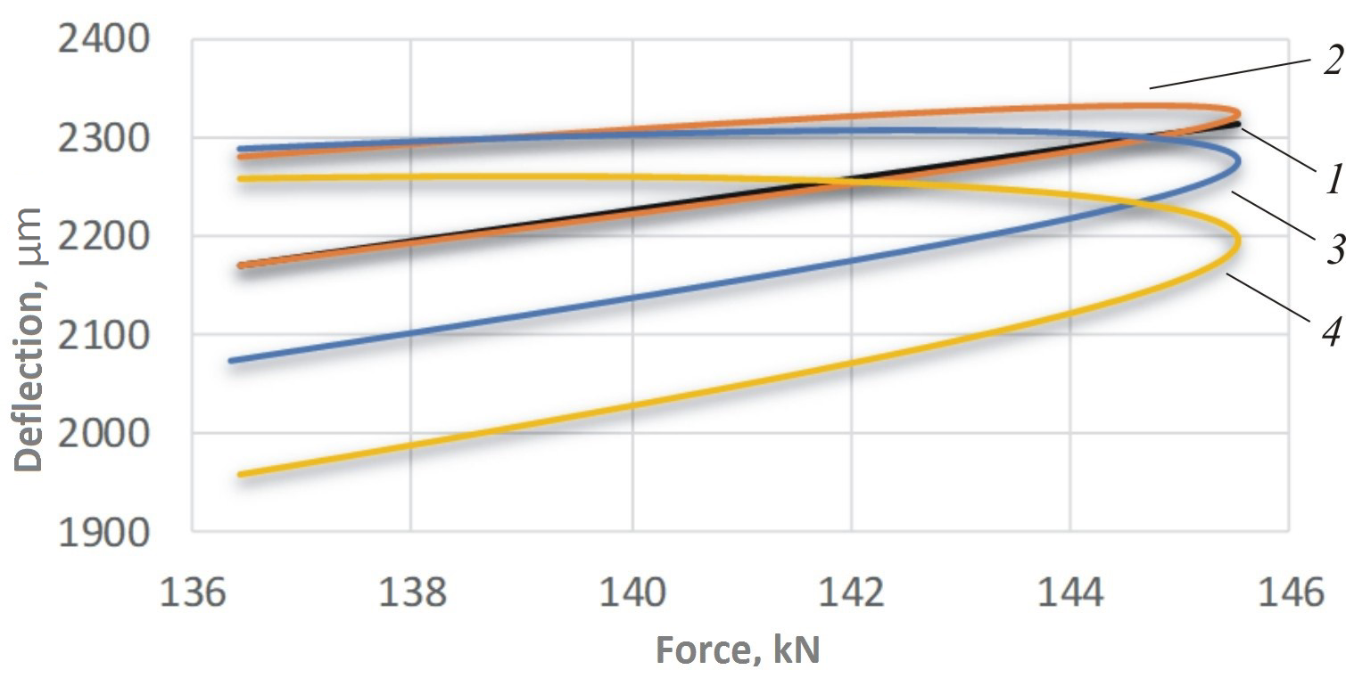
Fig. 4. Deflection of rail track
according
to modeling:
1
– statics; 2
– 80 km/h; 3
– 160 km/h; 4
– 240
Formula (6)
shows the analytic dependence of the deflection on the force. Thus,
the track characteristics can be determined as a result of
approximating the data array of deflections obtained by modeling ( )
by function (6). Approximation algorithm according to criterion of
the least squares:
)
by function (6). Approximation algorithm according to criterion of
the least squares:
 (7)
(7)
The
calculation results are summarized in the Table 1. They make it
possible on reasonable grounds to set the rail track characteristics
for the rolling stock modeling according to Lagrange-d'Amberm
principle. Analysis of results showed that application of reduced
mass of track objects in such models is appropriate in cases when
there is no complete deflection of the rail occurring at
a
sufficiently high speed [8], or in cases of simulation of
stress-strain state of directly separate elements of the rail track.
Originality and Practical
Value
Theoretically proved stiffness
and dissipation coefficients of the rail track for calculations of
rolling stock dynamics in modern models based on the
Lagrange-d'Alamber equation systems are obtained. The established
values as opposed to those given in other sources have a
substantiated dependence on the track structure and movement speed.
Table 1
Characteristics
of railway track as a support when interacting with a wheel
|
,
MPa
|
Indicator
|
Movement
speed, km/h
|
|
80
|
120
|
160
|
200
|
240
|
280
|
|
21
|
,
MN/m
|
47.4
|
48.2
|
49.5
|
51.2
|
53.2
|
55.3
|
|
,
kN s/m
|
100
|
70
|
60
|
40
|
40
|
40
|
|
32
|
,
MN/m
|
62.6
|
63.1
|
63.9
|
65.0
|
66.2
|
67.7
|
|
,
kN s/m
|
130
|
80
|
70
|
60
|
50
|
50
|
|
57
|
,
MN/m
|
97.2
|
97.9
|
98.6
|
99.4
|
100.4
|
101.8
|
|
,
kN s/m
|
210
|
160
|
110
|
90
|
80
|
70
|
Conclusions
The stiffness and dissipation
coefficients of the rail track as a support reduced to interaction
with the wheel in the models of vehicle movement are determined not
only by the elasticity of the underrail base layers, but also have a
direct and inverse dependence on the movement speed, respectively.
The approaches of rail track
representation in the rolling stock models, described by the
equation systems based on the Lagrange-d'Alamber principle are
expanded. The value of rigidity and dissipation coefficients of the
railway track depending on its design and speed are obtained.
List of reference links
Вершинский, С. В. Динамика вагона / С.
В. Вершинский, В. Н. Данилов, И. И. Челноков.
– Москва : Транспорт, 1972. – 304 с.
Даніленко, Е. І. Залізнична колія :
підруч. для вищ. навч. закл. :
у 2 т. / Е. І. Даніленко. – Київ :
Інпрес, 2010. – Т. 2. – 456 с.
Даренский, А. Н. Моделирование
взаимодействия пути и подвижного
состава при дискретном подрельсовом
основании в зоне рельсовых стыков / А.
Н. Даренский, А. В. Клименко // Інформ.-керуючі
системи на залізн. трансп. – 2012. – № 4
(101). – С. 15–22.
Курган, М. Підготовка колії для підвищення
швидкості руху поїздів / М. Курган, Д.
Курган, Н. Хмелевська // Укр.
залізниці. – 2017.
– № 9/10. – С. 14–21.
Курган, М. Б. Теоретичні основи
впровадження високошвидкісного руху
поїздів в Україні :
монографія / М. Б. Курган, Д. М. Курган
; Дніпропетр. нац. ун-т залізн. трансп.
ім. акад. В. Лазаряна. – Дніпро
: ДНУЗТ,
2016. – 283 с.
Connolly, D. P. Use of Conventional Site
Investigation Parameters to Calculate Critical Velocity of Trains
from Rayleigh Waves / D. P. Connolly, M. C. Forde //Transportation
Research Record: Journal of the Transportation Research Board. –
2015. – Vol. 2476. – Р.
32–36. doi:
10.3141/2476-05.
Kouroussis, G. A combined numerical/experimental
prediction method for urban railway vibration /
G. Kouroussis,
K. E. Vogiatzis, D. P. Connolly //Soil Dynamics and Earthquake
Engineering. – 2017. –
Vol. 97. – Р. 377–386.
doi: 10.1016/j.soildyn.2017.03.030.
Kurhan, D. M. Features of perception of loading
elements of the railway track at high speeds of the movement /
D. M. Kurhan // Наука та
прогрес транспорту.
– 2015. – № 2 (56). – С.
136–145.
doi:
10.15802/stp20-15/42172.
Meli, E. An innovative wheel–rail contact
model for railway vehicles under degraded adhesion conditions /
E. Meli,
A. Ridolfi //Multibody System Dynamics. – 2015. – Vol. 33.
– Іss. 3.
– Р.
285–313.
doi: 10.1007/s11044-013-9405-4.
Railway construction / Sz. Fisher, B. Eller, Z.
Kada, A. Németh. –
Győr : Universitas-Győr
Nonprofit Kft.,
2015. – 334
p.
Study of ground vibrations induced by railway
traffic in a 3D FEM model formulated in the time domain:
experimental validation / J. F. Ruiz, P. A. Costa, R. Calçada [et
al.] // Structure and Infrastructure Engineering. – 2016.
– Vol.
13. – Iss.
5. – Р.
652–664.
doi:
10.1080/15732479.2016.11-72649.
М. Б. Курган1, Д. М. курган2*
1Каф.
«Проектування і будівництво доріг»,
Дніпропетровський національний
університет залізничного транспорту
імені академіка В. Лазаряна,
вул.
Лазаряна, 2, Дніпро, Україна, 49010, тел.
+38 (056) 373
15 48,
ел. пошта kunibor@gmail.com
,
ORCID
0000-0002-8182-7709
2*Каф. «Колія та
колійне господарство», Дніпропетровський
національний
університет залізничного
транспорту імені академіка В. Лазаряна,
вул. Лазаряна, 2, Дніпро, Україна, 49010,
тел. +38 (056) 373
15 42,
ел. пошта kurhan.d@gmail.com
,
ORCID
0000-0002-9448-5269
ПРЕДСТАВЛЕННЯ ЗАлізничної
колії
в МАТЕМАТИЧНій моделі руху
екіпажів
Мета. Задачі
моделювання взаємодії колії та рухомого
складу є базовими для більшості напрямків
сучасних наукових досліджень залізничного
транспорту. Складання моделі за принципом
Лагранжа-д’Аламбера знайшло широке
застосування для вирішення задач
динаміки рухомого складу. Представлення
залізничної колії у моделі руху екіпажів
може здійснюватися декількома способами,
які, серед іншого, будуть відрізнятися
різною деталізацію. Метою даної роботи
є створення методики представлення
залізничної колії у математичних
моделях взаємодії з рухомим складом
та отримання практичних результатів
для різних характеристик і конструкцій
колії на рівні максимальної швидкості.
Методика.
Задача дослідження складається з
визначення таких характеристик колії:
приведена маса, коефіцієнт жорсткості,
коефіцієнт дисипації. Як
інструмент для її розв’язання була
застосована модель напружено-деформованого
стану залізничної колії, основана на
поєднанні рівнянь поширення пружної
хвилі для опису геометрії обрису частини
простору системи, що залучена до
взаємодії на даний момент часу, та
рівнянь динамічної рівноваги її
деформації. Це дає можливість урахування
динаміки прогину підрейкової основи,
що особливо важливо для умов пасажирського
руху, який може відбуватися з високою
швидкістю. Результати.
Отримані теоретично
обґрунтовані коефіцієнти жорсткості
та дисипації залізничної колії для
розрахунків динаміки рухомого складу
в сучасних моделях на основі систем
рівнянь, складених за принципом
Лагранжа-д’Аламбера. Встановлені
значення, на відміну від наведених в
інших джерелах, мають обґрунтовану
залежність, що поєднує конструкції
колії та швидкості руху.
Наукова новизна.
Розширені підходи представлення
залізничної колії у моделях рухомого
складу, описаних системами рівнянь за
принципом Лагранжа-д’Аламбера.
Розроблена методика визначення
характеристик залізничної колії для
таких моделей за результатами варіантних
розрахунків динамічного прогину рейки
від проходження колеса. Практична
значимість. Авторами
отримані значення коефіцієнтів
жорсткості й дисипації залізничної
колії залежно від її конструкції та
швидкості руху для практичного
застосування у відповідних моделях
взаємодії колії і рухомого складу.
Ключові слова: залізнична колія;
взаємодія колії та рухомого складу;
модель залізничної колії; жорсткість
колії; дисипація колії; динамічний
прогин колії; пасажирський рух
Н. Б. Курган1, Д. Н. курган2*
1Каф.
«Проектирование и строительство дорог»,
Днепропетровский национальный
университет железнодорожного транспорта
имени академика В. Лазаряна,
ул. Лазаряна,
2, Днипро, Украина, 49010, тел. +38 (056) 373 15 48,
эл. почта kunibor@gmail.com,
ORCID 0000-0002-8182-7709
2*Каф. «Путь и
путевое хозяйство», Днепропетровский
национальный университет
железнодорожного
транспорта имени
академика В. Лазаряна, ул. Лазаряна, 2,
Днипро, Украина, 49010, тел. +38 (056) 373 15 42,
эл. почта kurhan.d@gmail.com, ORCID 0000-0002-9448-5269
Представление железнодорожного
пути
в математической модели движения
экипажей
Цель. Задачи
моделирования взаимодействия пути и
подвижного состава являются базовыми
для большинства направлений современных
научных исследований железнодорожного
транспорта. Составление модели по
принципу Лагранжа-д’Аламбера нашло
широкое применение для решения задач
динамики подвижного состава. Представление
железнодорожного пути в модели движения
экипажей может осуществляться несколькими
способами, которые, среди прочего, будут
отличаться детализацией. Целью данной
работы является создание методики
представления железнодорожного пути
в математических моделях взаимодействия
с подвижным составом и получение
практических результатов для разных
характеристик, конструкций пути на
уровне максимальной скорости. Методика.
Задача исследования
состоит из определения таких характеристик
пути:
приведенная масса, коэффициент жесткости
и коэффициент диссипации. В качестве
инструмента для ее решения была
использована модель напряженно-деформированного
состояния железнодорожного пути,
основанная на совместном использовании
уравнений распространения упругих
волн для описания геометрии очертания
части пространства системы, которая
задействована во взаимодействии на
данный момент времени, и уравнений
динамического равновесия ее деформации.
Это дает возможность учесть динамику
прогиба подрельсового основания, что
особенно важно для условий пассажирского
движения, которое может осуществляться
с высокой скоростью. Результаты.
Получены теоретически обоснованные
коэффициенты жесткости и диссипации
железнодорожного пути для расчетов
динамики подвижного состава в современных
моделях на основе систем уравнений,
составленных по принципу Лагранжа-д’Аламбера.
Установленные значения, в отличие от
приведенных в других источниках, имеют
обоснованную зависимость, которая
объединяет конструкции пути и скорости
движения. Научная
новизна. Расширены
подходы представления железнодорожного
пути в моделях подвижного состава,
описанных системами уравнений по
принципу Лагранжа-д’Аламбера. Разработана
методика определения характеристик
железнодорожного пути для таких моделей
по результатам вариантных расчетов
динамического прогиба рельса от
прохождения колеса. Практическая
значимость. Авторами
получены значения коэффициентов
жесткости и диссипации железнодорожного
пути в зависимости от конструкции и
скорости движения для практического
использования в соответствующих моделях
взаимодействия пути и подвижного
состава.
Ключевые слова: железнодорожный
путь; взаимодействия пути и подвижного
состава; модель железнодорожного пути;
жесткость пути; диссипация пути;
динамический прогиб пути; пассажирское
движение
REFERENCES
Vershinskiy,
S. V., Danilov, V. N., & Chelnokov, I. I. (1972). Dinamika
vagona. Moscow: Transport. (in
Russian)
Danilenko,
E. I. (2010). Zaliznychna koliia
[Textbook] (Vol. 2). Kyiv: Inpres. (in Ukrainian)
Darenskiy,
A. N., & Klimenko, A. V. (2012). Modelirovaniye vzaimodeystviya
puti i podvizhnogo sostava pri diskretnom podrelsovom osnovanii v
zone relsovykh stykov. Informacijno-kerujuchi
systemy na zaliznychnomu transporti,
4(101),
15-22. (in Russian)
Kurhan,
M., Kurhan, D., & Khmelevska, N. (2017). Pidhotovka kolii dlia
pidvyshchennia shvydkosti rukhu poizdiv. Ukrainska
zaliznytsia, 9-10(51-52), 14-21. (in
Ukrainian)
Kurhan,
M. B., & Kurhan, D. M. (2016). Teoretychni
osnovy vprovadzhennia vysokoshvydkisnoho rukhu poizdiv v Ukraini
[Monograph]. Dnipro: Dnipropetrovsk National University of Railway
Transport named after Academician V. Lazaryan. (in
Ukrainian)
Connolly,
D. P., & Forde, M. C. (2015). Use of Conventional Site
Investigation Parameters to Calculate Critical Velocity of Trains
from Rayleigh Waves. Transportation
Research Record: Journal of the Transportation Research Board,
2476,
32-36. doi: 10.3141/2476-05. (in English)
Kouroussis,
G., Vogiatzis, K. E., & Connolly, D. P. (2017). A combined
numerical/experimental prediction method for urban railway
vibration. Soil Dynamics and
Earthquake Engineering, 97,
377-386.
doi: 10.1016/j.soildyn.2017.03.030. (in English)
Kurhan,
D. M. (2015). Features of perception of loading elements of the
railway track at high speeds of the movement. Science and
Transport Progress, 2(56), 136-145. doi:
10.15802/stp20-15/42172. (in English)
Meli,
E., & Ridolfi, A. (2015). An innovative wheel–rail contact
model for railway vehicles under degraded adhesion conditions.
Multibody System Dynamics, 33(3), 285-313.
doi: 10.1007/s11044-013-9405-4.
(in English)
Fisher,
S., Eller, B., Kada, Z., & Németh, A. (2015). Railway
Construction. Győr: Universitas-Győr
Nonprofit Kft. (in English)
Fernández
Ruiz, J., Costa, P. A., Calçada, R., Medina Rodríguez, L., &
Colaço, A. (2016). Study of ground vibrations induced by railway
traffic in a 3D FEM model formulated in the time domain:
experimental validation. Structure and Infrastructure
Engineering, 13(5), 652-664. doi:
10.1080/15732479.2016.1172649.
(in English)
Prof.
O. L. Tiutkin,
Dr. Sc. (Tech.) (Ukraine); Prof.
O. M. Darenskyi,
Dr. Sc. (Tech.) (Ukraine)
re-commended this article to be published
Received:
June 06,
2017
Accessed:
September 12,
2017
doi
10.15802/stp2017/118380 ©
M. B. Kurhan, D. M. Kurhan,
2017