ISSN
2307–3489 (Print), ІSSN 2307–6666 (Online)
Наука
та прогрес транспорту. Вісник
Дніпропетровського
національного
університету залізничного транспорту,
2017, № 5 (71)
рухомий
склад залізниць і тяга поїздів
UDC
[629.4.015:625.032.434]:531.3
O.
H. REIDEMEISTER1,
v. o. kalashnyk2,
O. A. SHYKUNOV3*
1Dep.
«Cars and
Cars Facilities»,
Dnipropetrovsk
National University of Railway Transport
named after Academician V.
Lazaryan, Lazaryan St., 2, Dnipro, Ukraine,
49010,
tel. +38
(056) 373 15 04, e-mail
reidemeister@mail.ru,
ORCID 0000-0001-7490-7180
2Dep.
«Cars and
Cars Facilities»,
Dnipropetrovsk
National University of Railway Transport
named after Academician V.
La-zaryan, Lazaryan St., 2, Dnipro, Ukraine,
49010,
tel.
+38 (056) 793 19 16, e-mail kv47@i.ua,
ORCID
0000-0002-8073-4631
3*Dep.
«Cars and
Cars Facilities»,
Dnipropetrovsk
National University of Railway Transport
named after Academician V.
La-zaryan, Lazaryan St., 2, Dnipro, Ukraine,
49010,
tel. +38
(056) 373 15 04, e-mail
tri_s@ua.fm,
ORCID 0000-0002-8256-2634
METHOD OF
CONSTRUCTING THE DYNAMIC
MODEL OF MOVEMENT OF THE MULTI-MASS
SYSTEM
Purpose.
The scientific work is intended to develop a methodology for
describing the structure of the railway vehicles (they are considered
as a system of rigid bodies connected by rigid, elastic and
dissipative elements), which would allow us to obtain the equations
of motion in an easily algorithmized way.
Methodology. When constructing the
model, authors tend to ensure that its structure reflects the
structure of the mechanical system, that is, parts of the model must
correspond to parts of the car. In this case, the model takes the
form of a hierarchically organized graph whose vertices correspond to
the bodies, attachment points of the connecting elements and to the
connecting elements themselves, and the edges describe the sets of
processes that are related to the incident vertexes. As a rule, these
are movements and forces: for the edge between the body and the
attachment point they are generalized movements of the body and the
general forces acting on it; for the edge between the attachment
point and the connecting element - the movements of the point and the
forces arising in the element. To each vertex there corresponds a
group of equations describing the motion of the system. The nature of
the equations depends on the type of the vertex. For the body it is
the equations of body motion; for the point - the expressions for the
point displacements through generalized displacements of the body and
generalized forces acting on the body, through the forces arising in
the connecting element; for the connecting element - the expression
for the forces arising in it through the deformation of the element.
The graph can be regarded as oriented. The direction of the edge is
chosen in such a way that for each vertex the values on the
right-hand side of the vertex-associated equation would correspond to
the incoming edge, and in the left-hand side - to the outgoing edge.
Findings. A
technique for constructing a dynamic model of oscillations of railway
vehicles as a system of rigid bodies is developed on the basis of
their description using hierarchically organized graphs. The
technique was tested to construct a model of spatial oscillations of
a 4-axle freight car with an axial load of 25 tons in Simulink
package. Originality.
For the first time, a
technique has been developed for describing the structure of a
railway vehicle using a hierarchical graph, which makes it possible
to obtain equations of motion in an easily algorithmized manner.
Practical value.
The proposed methodological approach will allow, after creating a
library of bodies and connecting elements, to significantly reduce
the time spent on modeling the oscillations of different vehicles.
Keywords:
oscillation model; railway vehicle; multi-mass system; graph
Introduction
At
present, the approach to constructing models of car oscillations is
well known and tested for assessing the car running qualities and
dynamic loading of elements [12]. The car is considered as a set of
solid bodies [1], connected by rigid, elastic, viscous, dissipative
elements [10, 11, 13]. As a rule, the angles of rotation are
considered small values, after which the compilation of the
equations of motion becomes a routine procedure, which it is
advisable to deliver into charge of the computer.
Let
us consider one of the possible approaches to the solution of this
problem, for this we will present a semi-formal way of describing
the model and the rules of compiling the equations of motion.
Actually, we will not be interested in the solution of the
equations, since for these purposes there are universal packages of
applied programs Simulink [6], Simscape, OpenModelica, Dymola (the
last two packages implement the language of the description of
dynamical systems Modelica [9]) and so on.
Purpose
To
develop a methodology for describing the structure of the railway
vehicles (they are con-sidered as a system of rigid bodies connected
by rigid, elastic and dissipative elements), which would allow us to
obtain the equations of motion in an easily algorithmized way.
Methodology
When
building a model, we strive to ensure that its structure reflects
the structure of the mechanical system (car), that is, parts of the
model must cor-respond to parts of the car. In this case, the model
takes the form of a hierarchically organized graph whose vertices
correspond to the bodies and connecting elements, and the edges
describe the sets of processes that that are related to the incident
to edge vertices [7]. An example of the general structure of the
model is shown in Figure 1.

Fig. 1.
Car body: a
– vertex representing, b
– its internal structure. Pt1 and Pt2 are attachment points of
pairs «Centre
plate - Centre pad»
As a rule, a set of generalized
displacements and corresponding generalized forces correspond to the
edge.
For the edge, causality
conditions can be defined (for example, if the force is considered
as a function of displacements) or not (forces and displacements are
related by implicit relations). The difference between the two types
of edges is not fundamental and, if desired, one can write down the
formal rules for determining the causality relation.
To
describe the model-building rules, we use the inductive approach and
consider the basic types of subsystems and the corresponding
equations. In doing so, we will try to match the set of equations to
the node, and the set of variables to the edge.

Fig.
2. Fragment of «Bogie»
subsystem
Figure
2 shows a fragment of the «Bogie»
subsystem,
in which the bolster NB
is
connected to the solebars BR1,
BR2 with
the spring suspension unit RP1,
RP2.
The motion of such a subsystem is described by the equations that
can be conveniently divided into the following groups:
1) Equations
of motion of bodies;
2) Equations
expressing the movement of the attachment points of the connecting
elements through the movements of the bodies;
3) Equation
of the relationship between the deformation of the connecting
element and the force that arises in it.
The
last group of equations refers to the connecting elements, the first
two to the bodies. In view of the fact that the parameters of the
equations of the first two groups are different, it is advisable to
equip each body with an internal structure, as shown in Fig. 3,
using the example of bolster.

Fig. 3. Bolster.
Internal structure of the node
The inner
vertex «Body»
corresponds to the body motion equations. Internal vertices RP1,
RP2, PP, SK1, SK2 - to the attachment
points of corresponding connecting elements: spring suspension, pair
«Centre plate - Centre pad», side bearing. These classes of
vertices (for the body, for attachment points of the connecting
element and for the connecting element itself) are the basic ones
for building the car model. We will dwell in detail on each of them.
The
vertex representing the motion equations of the body, whose
principal central axes of inertia are parallel to the coordinate
axes, is shown in Fig. 4.
This
vertex can be incident with several edges, each of which is
associated with a set of gene-ralized displacements
 and generalized forces
 .
The edges connect the vertex «Body»
with the vertex «Point».
.
The edges connect the vertex «Body»
with the vertex «Point».
The
physical meaning of the processes
–is the generalized displacements of the body.
The
vectors
correspond to generalized forces acting on the body at the j-th
point. The body motion equation includes the sums of the components
of these vectors, and the motion equations themselves take the form:
 (1)
(1)
where
 – body mass,
 – main central moments of inertia.
Variables
corresponding to displacements are called variables of the potential
type, and processes corresponding to the forces are variables of the
current type.
These names refer to Kirchhoff's laws for electrical circuits and to
the fact that the movements in the edges incident to one vertex are
equated to each other, and the forces are added together.

Fig.
4. Vertex «Body
motion equations»
The
vertex representing the «Point»
(Figure 5) is responsible for transforming the displacements and
forces acting on the body (superscript «0») into the displacements
of the point and the force applied to it (superscript «1»). The
parameters of the vertex are the coordinates of the point
 in the coordinate system, whose origin is in the center of gravity
of the body. At small angles of rotation, the expressions that
determines the relationship between the values
in the coordinate system, whose origin is in the center of gravity
of the body. At small angles of rotation, the expressions that
determines the relationship between the values
 and
and
 take the form:
 (2)
(2)
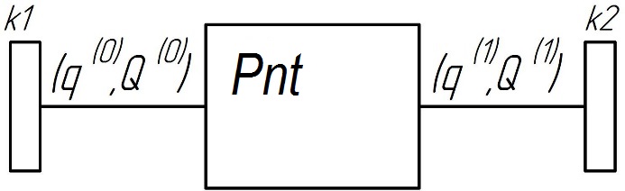
Fig.
5. Vertex «Point»
The
«Connecting element»
connects the «Points»
of two «Bodies»,
Figure 6.

Fig.
6. Vertex «Connecting
element»
The deformation of the
connecting element is the difference
 (3)
(3)
The
force
 ,
arising in the connecting element depends on the deformation
,
arising in the connecting element depends on the deformation
 .
The expression for the force depends on the type of the connecting
element. For example, for a linear spring of rigidity
.
The expression for the force depends on the type of the connecting
element. For example, for a linear spring of rigidity
 ,
operating in a vertical direction
,
operating in a vertical direction
 (4)
(4)
It
is convenient to assume that the force
acts on
the Body-0 from the side of the Body-1. In this case
 ,
,
 .
.
By
combining the described types of vertices, it is possible to present
in a compact and visual form a model of car oscillations, suitable
for direct formation of the motion equations.
Let
us consider the implementation of the described approach for
building a model in the Simulink package. In this case, the body,
point and connecting element are conveniently represented as
subsystems. As an example, Figure 7 shows the Simulink scheme for
the subsystem «Bolster».

Fig.
7. Subsystem «Bolster»
in Simulink model
A
non-trivial matter is the question of comparing each edge with the
direction of signal propagation, which is chosen so that for
explicit expression of some values through other the argument is the
input, and the function is the output.
Having examined the expression
(2), we see that the directions for displacements and the directions
for forces in one edge are opposite to each other. The direction of
propagation for different signals is given in Table 1.
Table 1
Directions of
signal propagation
|
Vertex
class
|
Process
|
Direction
|
|
Body
|
q(j)
|
output
|
|
Q(j)
|
input
|
|
Point
|
q(0)
|
input
|
|
Q(0)
|
output
|
|
q(1)
|
output
|
|
Q(1)
|
input
|
|
Connecting
element
|
q(0),
q(1)
|
input
|
|
Q(0),
Q(1)
|
output
|
Findings
The
use of the proposed method resulted in creation of a freight car
model, which consists of a body and two bogies. The bogies were
considered as a construction consisting of the following
subsystem-elements [2, 3]:
wheel
sets with box;
– solebars;
– bolster;
– springs
of the central spring unit (each two-row spring separately);
– friction
vibration dampers;
– axle-box
suspension;
– centre
pad;
– side
bearing.
Each
of these subsystems is independent and can be replaced with the
condition of preserving the geometric parameters of the connection
points of the element. This feature of the model is convenient to
use for changing the parameters in order to select their optimal
values.
The
bodies, with the exception of bolsters and bogie solebars, have 6
degrees of freedom; the angles of rotation are small. To better
estimate the dynamic loading of the bogie cast parts, the detailed
models of spring suspension (up to individual springs and friction
wedges, which are consi-dered as separate bodies of the system) and
axle box were developed.
The
model will be used to evaluate the dynamic loading of bogie elements
of the car with an axial load of 25 tons [8], in order to clarify
the loads arising during operation [4, 5, 14]. Vertical forces
acting in the axle box when the car moves along a straight section
of the track at 120 km/h speed are shown in Figure 8.
Originality and practical
value
For the first time, a methodical
approach to creating dynamic models of railway vehicles based on
their description using hierarchically organized graphs was
proposed.
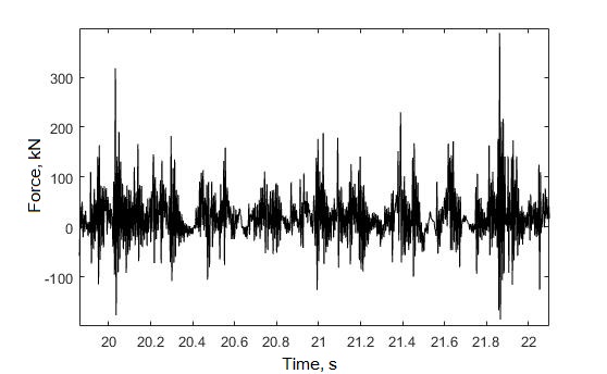
Fig.
8. Vertical
forces
in
the
axle
box of
gondola
car
with
axle
load
of
25 tons,
speed
of
120 km/h
This
methodological approach will allow, after creating a library of
bodies and connecting elements, to significantly reduce the time
spent on modeling the oscillations of different vehicles.
Conclusions
A
technique has been developed for describing the structure of a
railway vehicle using a hierarchical graph, which makes it possible
to obtain equations of motion in an easily algorithmized manner. The
vehicle is a system of rigid bodies connected by rigid, elastic and
dissipative elements. The technique was tested to construct a model
of spatial oscillations of a 4-axle freight car in the Simulink
package. Directions of further development: creation of the library
of bodies and connecting elements, detailed presentation of the
geometry of track, the models of track superstructure and wheel-rail
interaction.
LIST OF REFERENCE LINKS
Виттенбург,
Й. Динамика систем твердых тел / Й.
Виттенбург. – Москва : Мир, 1980. – 294 с.
Динамические
качества грузовых вагонов, имеющих
тележки с диагональными связями / Е.
П. Блохин, К. Т. Алпысбаев, Р. Б. Грановский
[и др.] // Вісн. Східноукр. нац. ун-ту ім.
Володимира Даля. – 2012. – № 5, ч. 1. – С.
12–16.
Определение
допускаемых скоростей движения грузовых
вагонов по железнодорожным путям колеи
1520 мм / В. Д. Данович, В. В. Рыбкин, С. В.
Мямлин, А. Г. Рейдемейстер, А. П. Трякин,
Н. В. Халипова // Вісн. Дніпропетр. нац.
ун-ту залізн. трансп. ім. акад. В. Лазаряна.
– Дніпропетровськ, 2003. – Вип. 2. –
С. 77–86.
Определение
параметров пространственного нагружения
литых деталей тележки 18-9855 при проведении
стендовых испытаний / Д. В. Шевченко,
Т. С. Куклин, А. М. Орлова [и др.] // Техника
железных дорог. – 2016. – № 1 (33). – С.
68–74.
Рейдемейстер,
А. Г. Способы увеличения прочности
боковых рам трехэлементных тележек /
А. Г. Рейдемейстер, А. А. Шикунов // Наука
та прогрес транспорту. – 2015. – № 5 (59).
– С. 141–149.
doi:
10.15802/stp2015/55351.
Черных,
И. В. Simulink: Инструмент моделирования
динамических систем [Electronic
resource] /
И.
В. Черных. – Available
at:
http://matlab.exponenta.ru/simulink/book1/index.php.
– Title from
the screen.
– Accessed :
31.08.2017.
Borutzky,
W. Bond graph methodology: development and analysis of
multidisciplinary dynamic system models /
W. Borutzky. –
Sankt Augustin :
Springer Science & Business Media, 2009.
– 662 p.
Bubnov,
V. M. Dynamic performance of freight cars on bogies model 18-1711 /
V. M. Bubnov,
S.
V. Myamlin, N.
B.
Mankevych // Наука та прогрес
транспорту. – 2013. – № 4 (46). – С. 118–126.
doi: 10.15802/stp2013/16616.
Fritzson,
P. Introduction to modeling and simulation of technical and
physical systems with Modelica /
P.
Fritzson. –
Hoboken : John
Wiley & Sons, 2011. – 211
p.
Handbook
of railway vehicle dynamics / Edited
by S. Iwnicki. – Boca Raton : CRC
press, 2006. – 526 p.
Knothe, K. Rail
vehicle dynamics / K. Knothe, S. Stichel. – Cham : Springer,
2017. – 321 p.
Shabana,
A. A. Dynamics of multibody systems / A. A. Shabana. – Cambridge
: Cambridge university press, 2013. – 374 p.
Shabana,
A. A. Railroad vehicle dynamics: a computational approach / A. A.
Shabana, K. E. Zaazaa,
H.
Sugiyama. – Boca Raton : CRC press, 2007. – 343 p.
Shykunov,
O. A.
Three-Element Bogie Side Frame Strength / O. A.
Shykunov // Наука та прогрес транспорту. –
2017. – № 1 (67). – С. 183–193. doi:
10.15802/stp2017/92535.
О.
Г. РЕЙДЕМЕЙСТЕР1,
В. О. КАЛАШНИК2,
О. А. ШИКУНОВ3*
1Каф.
«Вагони та вагонне господарство»,
Дніпропетровській національний
університет залізничного
транспорту
імені академіка В. Лазаряна, вул.
Лазаряна, 2, Дніпро, Україна, 49010, тел.
+38 (056) 373 15 04,
ел. пошта reidemeister@mail.ru,
ORCID 0000-0001-7490-7180
2Каф. «Вагони та
вагонне господарство», Дніпропетровській
національний університет залізничного
транспорту імені академіка В. Лазаряна,
вул. Лазаряна, 2, Дніпро, Україна, 49010,
тел. +38
(056) 793 19 16,
ел. пошта
kv47@i.ua,
ORCID 0000-0002-8073-4631
3*Каф. «Вагони
та вагонне господарство», Дніпропетровській
національний університет залізничного
транспорту імені академіка В. Лазаряна,
вул. Лазаряна, 2, Дніпро, Україна, 49010,
тел. +38 (056) 373 15 04,
ел. пошта
tri_s@ua.fm,
ORCID 0000-0002-8256-2634
МЕТОДИКА
ПОБУДОВИ ДИНАМІЧНОЇ МОДЕЛІ
РУХУ
БАГАТОМАСОВИХ СИСТЕМ
Мета.
У науковій роботі необхідно розробити
методику опису структури залізничних
екіпажів (розглядаються як система
твердих тіл, з’єднаних жорсткими,
пружними та дисипативними елементами),
яка дозволила б отримати рівняння руху
способом, що легко алгоритмізується.
Методика.
При побудові моделі автори прагнуть
до того, щоб її структура відображала
структуру механічної системи, тобто
частини моделі повинні відповідати
частинам вагона. При цьому модель
набуває форму ієрархічно організованого
графа, вершини якого відповідають
тілам, точкам кріплення з’єднувальних
елементів та самим з’єднувальним
елементам, а ребра описують сукупності
процесів, які мають відношення до
інцидентних ребру вершин. Як правило,
це переміщення та сили: для ребра між
тілом і точкою кріплення – узагальнені
переміщення тіла та діючі на нього
узагальнені сили; для ребра між точкою
кріплення й з’єднувальним елементом
– переміщення точки і сили, що виникають
в елементі. Кожній вершині відповідає
група рівнянь, що описують рух системи.
Характер рівнянь залежить від типу
вершини. Для тіла – рівняння руху тіла;
для точки – вирази переміщень точки
через узагальнені переміщення тіла й
узагальнених сил, що діють на тіло,
через сили, що виникають у з’єднувальному
елементі; для з’єднувального елемента
– вирази для сил, що виникають в ньому,
через деформації елемента. Граф може
розглядатися як орієнтований. Напрямок
ребра обирають таким чином, щоб для
кожної вершини величини, що стоять у
правій частині зіставлених вершині
рівнянь, відповідали ребру, що входить,
а в лівій – виходить. Результати.
Розроблено методику побудови динамічної
моделі коливань залізничних екіпажів
як системи твердих тіл на основі їх
опису за допомогою ієрархічно
організованих графів. Методика
випробувана для побудови моделі
просторових коливань 4-вісного вантажного
вагона з осьовим навантаженням 25 тс в
пакеті Simulink. Наукова
новизна. Вперше
розроблено методику опису структури
залізничного екіпажу за допомогою
ієрархічного графа, яка дозволяє
отримати рівняння руху способом, що
легко алгоритмізується. Практична
значимість. Запропонований
методичний підхід дозволить, після
створення бібліотеки тіл та з’єднувальних
елементів, значно скоротити витрати
часу на моделювання коливань різних
екіпажів.
Ключові
слова: модель коливань; залізничний
екіпаж; багатомасова система; граф
А. Г.
РЕЙДЕМЕЙСТЕР1, В. А. КАЛАШНИК2,
А. А. ШИКУНОВ3*
1Каф.
«Вагоны и вагонное хозяйство»,
Днепропетровский национальный
университет железнодорожного
транспорта
имени академика В. Лазаряна, ул. Лазаряна,
2, Днипро, Украина, 49010, тел. +38 (056) 373 15 04,
эл. почта reidemeister@mail.ru, ORCID
0000-0001-7490-7180
2Каф. «Вагоны и
вагонное хозяйство», Днепропетровский
национальный университет железнодорожного
транспорта имени академика В. Лазаряна,
ул. Лазаряна, 2, Днипро, Украина, 49010, тел.
+38 (056) 793 19 16,
эл. почта kv47@i.ua, ORCID
0000-0002-8073-4631
3*Каф. «Вагоны и
вагонное хозяйство», Днепропетровский
национальный университет железнодорожного
транспорта имени академика В. Лазаряна,
ул. Лазаряна, 2, Днипро, Украина, 49010, тел.
+38 (056) 373 15 04,
эл. почта tri_s@ua.fm,
ORCID 0000-0002-8256-2634
МЕТОДИКА
ПОСТРОЕНИЯ ДИНАМИЧЕСКОЙ МОДЕЛИ
ДВИЖЕНИЯ
МНОГОМАССОВОЙ СИСТЕМЫ
Цель.
В научной работе необходимо разработать
методику описания структуры железнодорожных
экипажей (рассматриваются как система
твердых тел, соединенных жесткими,
упругими и диссипативными элементами),
которая позволила б получить уравнения
движения легко алгоритмизируемым
способом. Методика.
При построении модели авторы стремятся
к тому, чтобы ее структура отражала
структуру механической системы, то
есть части модели должны соответствовать
частям вагона. При этом модель приобретает
форму иерархически организованного
графа, вершины которого соответствуют
телам, точкам крепления соединительных
элементов и самим соединительным
элементам, а ребра описывают совокупности
процессов, которые имеют отношение к
инцидентным ребру вершинам. Как правило,
это перемещения и силы: для ребра между
телом и точкой крепления – обобщенные
перемещения тела и действующие на него
обобщенные силы; для ребра между точкой
крепления и соединительным элементом
– перемещения точки и силы, возникающие
в элементе. Каждой вершине соответствует
группа уравнений, описывающих движение
системы. Характер уравнений зависит
от типа вершины. Для тела – уравнения
движения тела; для точки – выражения
перемещений точки через обобщенные
перемещения тела и обобщенных сил,
действующих на тело, через силы,
возникающие в соединительном элементе;
для соединительного элемента – выражения
для сил, возникающих в нем, через
деформации элемента. Граф может
рассматриваться как ориентированный.
Направление ребра выбирают таким
образом, чтобы для каждой вершины
величины, стоящие в правой части
сопоставленных вершине уравнений,
соответствовали входящему ребру, а в
левой – исходящему. Результаты.
Разработана методика
построения динамической модели колебаний
железнодорожных экипажей как системы
твердых тел на основе их описания с
помощью иерархически организованных
графов. Методика опробована для
построения модели пространственных
колебаний 4-осного грузового вагона с
осевой нагрузкой 25 тс в пакете Simulink.
Научная новизна.
Впервые разработана методика описания
структуры железнодорожного экипажа с
помощью иерархического графа, которая
позволяет получить уравнения движения
легко алгоритмизируемым способом.
Практическая значимость.
Предложенный методический подход
позволит, после создания библиотеки
тел и соединительных элементов,
значительно сократить затраты времени
на моделирование колебаний различных
экипажей.
Ключевые
слова: модель колебаний; железнодорожный
экипаж; многомассовая система; граф
REFERENCES
Vittenburg,
Y. (1980). Dinamika sistem tverdykh
tel. Moscow:
Mir.
Blokhin,
Y. P., Alpysbaev, K. T., Granovskiy, R. B., Dzichkovskiy, Y.,
Krivchikov, A., Fedorov, Y. F. (2012). Dinamicheskie kachestva
gruzovykh vagonov, imeyushchikh telezhki s diagonalnymi svyazyami.
Visnik of the Volodymyr Dahl East
Ukrainian National University, 5 (1),
12-16.
Danovich,
V. D., Rybkin, V. V., Myamlin, S. V., Reydemeyster, A. G., Tryakin,
A. P., Khalipova,
N.
V. (2003). Determination
of permissible speeds of freight cars on railroad tracks 1520 mm.
Bulletin of Dnipropetrovsk National
University of Railway Transport, 2,
77-86.
Shevchenko,
D. V., Kuklin, T. S., Orlova, A. M., Savushkin, R. A., Dmitriev, S.
V., & Belyankin,
A.
V. (2016). Opredeleniye
parametrov prostranstvennogo nagruzheniya litykh detaley telezhki
18-9855 pri provedenii stendovykh ispytaniy. Railway
Equipment Magazine,
1 (33),
68-74.
Reidemeister,
O. H., & Shykunov, O. A. (2015). Strength increase methods of
the side frame of the bogie in three-piece
trucks. Science and Transport
Progress, 5
(59), 141-149. doi:10.15802/stp2015/55351
Chernykh,
I. V. (n.d.). Simulink: Instrument
modelirovaniya dinamicheskikh system.
MATLAB.Exponenta!
Retrieved from http://matlab.exponenta.ru/simulink/book1/index.php
Borutzky,
W. (2010). Bond
graph methodology: development and analysis of multidisciplinary
dynamic system models. Sankt Augustin: Springer Science &
Business Media. doi:10.1007/978-1-84882-882-7
Bubnov,
V. M., Myamlin, S. V., & Mankevych, N. B. (2013). Dynamic
performance of freight cars on bogies model 18-1711. Science
and Transport Progress, 4
(46), 118-126. doi:10.15802/stp2013/16616
Fritzson,
P. (2011). Introduction to modeling
and simulation of technical and physical systems with Modelica.
Hoboken: John Wiley & Sons. doi:10.1002/9781118094259
Iwnicki,
S. (Ed.). (2006). Handbook
of railway vehicle dynamics.
Boca Raton: CRC press.
Knothe,
K., & Stichel, S. (2017). Rail
vehicle dynamics. Cham: Springer.
doi:10.1007/978-3-319-45376-7
Shabana,
A. A. (2013). Dynamics of multibody
systems. Cambridge: Cambridge
university press.
Shabana,
A. A., Zaazaa, K. E., & Sugiyama, H. (2007). Railroad
vehicle dynamics: A computational approach.
Boca Raton: CRC press.
Shykunov,
O. A. (2017). Three-element bogie side frame strength. Science
and Transport Progress, 1
(67), 183-193. doi:10.15802/stp2017/92535
Prof.
S. V. Myamlin,
D. Sc. (Tech.), (Ukraine); PhD
Tech., Senior Research Associate T.
V. Sheleiko (Ukraine)
recommended this article to be published
Received:
May 17,
2017
Accessed:
Sept. 21,
2017
doi
10.15802/stp2017/112921 © O.
H. Reidemeister, V. O. Kalashnyk, O. A. Shykunov,
2017