ISSN
2307–3489 (Print), ІSSN
2307–6666
(Online)
Наука
та прогрес транспорту. Вісник
Дніпропетровського
національного університету залізничного
транспорту, 2017, № 4 (70)
рухомий
склад залізниць і тяга поїздів
РУХОМИЙ
СКЛАД ЗАЛІЗНИЦЬ І ТЯГА ПОЇЗДІВ
UDC
629.4.048.7
E.
V. BILOSHYTSKYI1*
WAYS TO MANAGE
HEATING INERTIA
1*Project
Design and Technological Bureau,
Dnipropetrovsk National University of
Railway Transport named after
Academician V. Lazaryan, Lazaryan
St., 2, Dnipro, Ukraine, 49010,
tel. +38 (056) 371 51 12, e-mail
beloshickij@rambler.ru,
ORCID 0000-0002-2424-8479
Purpose. The
research paper proposes to estimate the effect of heat inertia of the
water heating system, in transient operation modes, on the
temperature condition in the passenger car, as well as to offer
technical solutions intended to reduce the heating system inertia
effect and to maintain a stable temperature condition in the
passenger car premises in transitional modes of the heating system.
Methodology. The author developed the method for controlling
the heat transfer of heating system pipes with the help of regulating
casing. To control the heating system and the heat transfer of
heating pipes, two types of temperature control sensors were used in
the passenger car: certain sensors interacted with regulatory
casings, while the others interacted with high-voltage tubular
heating element control devices. To assess the efficiency of heat
interchange regulation of heating pipes and the heating system
control, with installed regulating casings, the operation of the
heating system with regulating casings and two types of sensors was
mathematically modelled. Mathematical modelling used the experimental
test data. The results of experimental tests and mathematical
modelling were compared. Findings. Currently in operated
passenger cars, control of heating appliances is not constructively
provided. Automatic maintenance of the set temperature in a passenger
car is limited to switching on and off of high-voltage tubular
heating elements. The use of regulating casings on heating pipes
allows reducing the effects of heat inertia and maintaining stable
thermal conditions in a passenger car, using the heating system as a
heat accumulator, and also provides the opportunity to realize an
individual control of air temperature in the compartment.
Originality. For the first time, the paper studied the
alternative ways of regulating the temperature condition in a
passenger car. Using of the heating system as a heat accumulator.
Practical value. The regulation of the heat transfers of
the heating pipes by regulating casings allows reducing the effect of
thermal inertia of the heating system on the temperature condition in
a passenger car, implementing individual adjustment of air
temperature in a compartment within 40% of the power of the heating
pipe section, using the heating system as a heat accumulator.
Keywords:
heating of passenger cars; free convection; heat transfer; heat
accumulator
Introduction
During
operation, it is practically impossible to maintain the required
heat transfer fluid temperature in the passenger car boiler. This is
due to the shutdown of high-voltage electric heating tubes of the
heating system. The reasons for the shutdown are different during
moving and standing with subsequent
heating, resulting in transient heating modes that cause temperature
fluctuations in passenger cars. This process is compounded by the
fact that during moving and standing of a passenger car the required
heating capacity of the heating system is different, the higher the
speed of the car, the more the required heating capacity of the
heating system increases, this is confirmed by the results
of the study [4],
Fig. 1.
Transitional
modes are compounded by the large heat inertia of the heating
system. The installed
high-voltage heating tubes also have heat inertia, which also
affects the inertia of the heating system. The installed sensors for
monitoring the temperature in the car have no correction for the
inertia of the heating system.
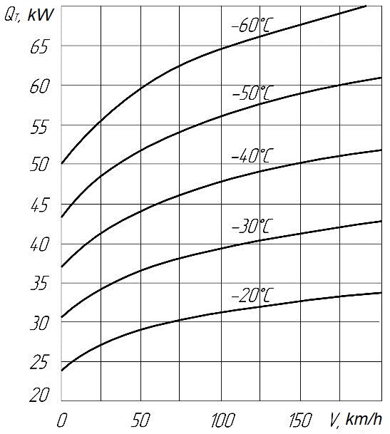
Fig. 1. Required
heating capacity of the passenger car heating system in relation to
traffic at various outdoor temperatures
Since 2004,
all types of cars are equipped with air-conditioning units [2]. The
water heating system
with smooth regulation of the boiler’s heat output in the range of
loads from «0» to 48.0 kW is proposed. For this purpose, the
boiler is equipped with three groups of electric heating: I group –
24.0 kW, 3 kV, II group – 12.0 kW, 3 kV, III group – 12.0 kW,
380 V. The third group of the boiler is connected to the air
conditioner converter circuit through the appropriate switching
devices. The converter provides for smooth regulation of the output
power from «0» to Pnom
(12 ÷ 17 kW). Therefore, the III group of the boiler will have
smooth power regulation from «0» to
 .
As a result, the entire range of heat output of the boiler will be
with smooth regulation.
.
As a result, the entire range of heat output of the boiler will be
with smooth regulation.
The disadvantage of the proposed
system is that the system can work qualitatively when heating the
boiler only with electricity.
The work [2]
considers the water heating system
with smooth regulation of heating output of heating pipes at boiler
combined heating. The system
is designed for smooth regulation and stabilization
of the heat transfer fluid temperature at the inlet to the heating
devices, respectively, at transient and steady-state modes,
stabilizing the air temperatures inside the car during cycling of
high-voltage heating groups of the boiler, and also when the boiler
is operated with solid fuel.
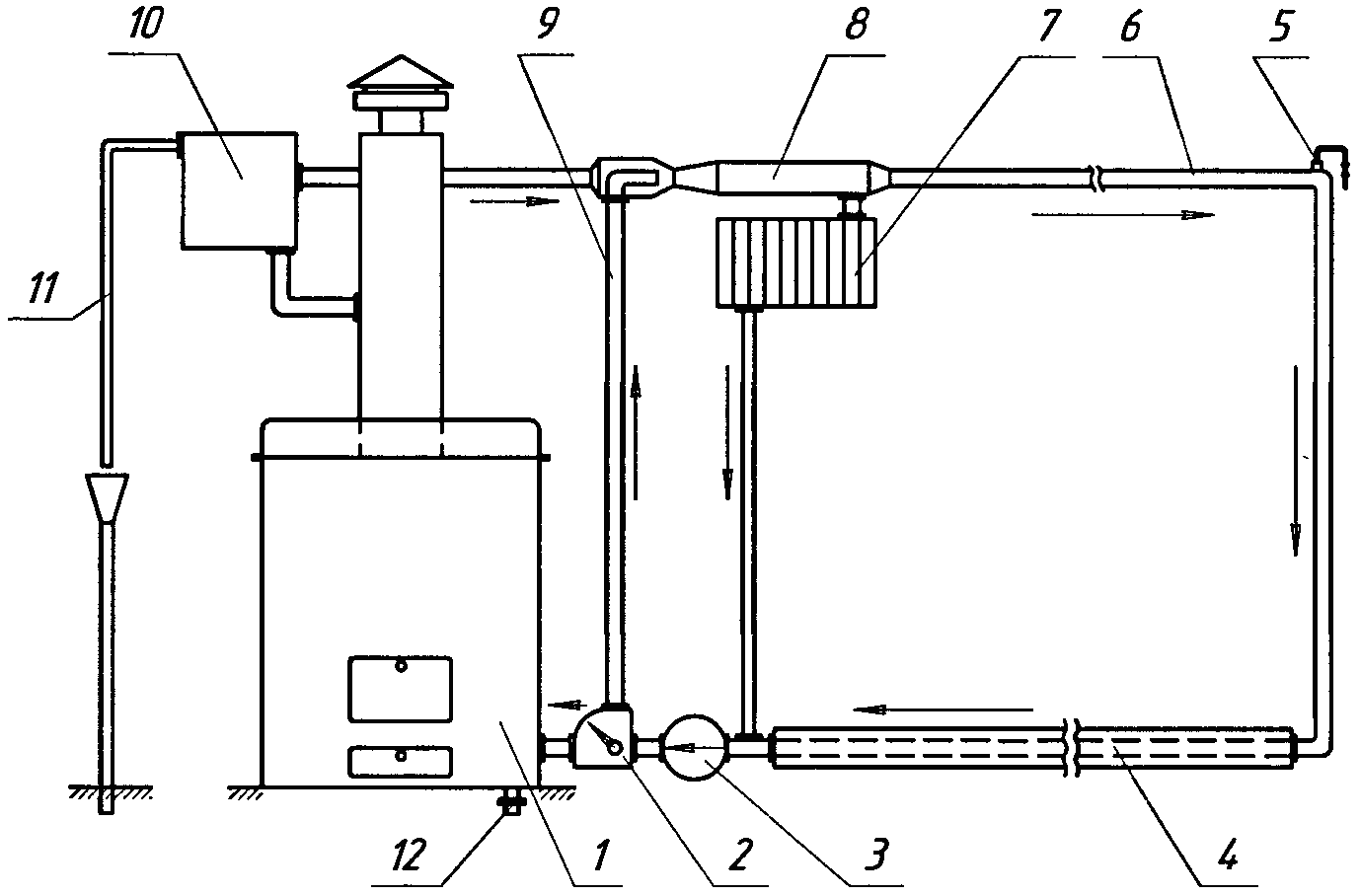
Fig. 2. Layout of
water heating with separation of flows: 1
– boiler; 2
– divisor; 3
– circulating pump; 4
– heating pipes; 5
– air line; 6
– feeding pipe; 7
– air heater; 8
– mixer;
9
– bypass pipe; 10
– expander; 11
– overflow pipe;
12
– drain plug
The principle
of operation of the system, whose layout is shown in Fig. 2,
consists in the separation of the heat transfer fluid flow at the
inlet to the boiler into two adjustable parts by the divider 2
with an electric drive. One part of
the flow returns to the boiler 1,
and the second one through the bypass pipe 9,
passing the boiler, goes to the mixer 8.
The movement of the heat transfer fluid through the system is
carried out by a circulation pump 3.
Depending on the required heating output
of the system, a heat transfer fluid with the required temperature
is fed into the heating devices through the mixer 8.
In this case, there is no need for strict maintenance of any value
of the heat transfer fluid temperature at the outlet from the
boiler.
This system can only work when
the circulation pump is on, which reduces its reliability.
The work [8]
proposes to use the heating system
as a cold and heat accumulator; the selection
of accumulated, cold or heat is assumed only through the water
heater, without additional conversion of the heating system. Using a
heating system as a cold accumulator is possible, but as a heat
accumulator without additional conversion is impossible, since the
heating system will work in the usual heating mode. The publication
of specialists
[1] is devoted to the interaction of heating and ventilation
systems; the work proposes to automate the operation of the water
heater to maintain
the set temperature, the outer air heated in the heater and fed by
the ventilation system.
Improvement of
the operation of refrigerating equipment of passenger cars in
transitional modes was considered in [11].
The study
[14] is aimed at
reducing the energy costs of modern light rail system Luas operating
in Dublin, Ireland, through the optimization of the heating and
ventilation system. The work [12]
studied the Swiss railroad vehicles of Swiss Rhaetian Railway (RhB).
The research is aimed at improving
the energy efficiency of life-support systems for railway vehicles,
by reducing the consumption
of outside air by way of controlling
 content in the air. The publications
[5, 9,
13]
are devoted to the improvement of air conditioning systems of modern
passenger cars. Problems of increasing the comfort of passenger
transportation are also examined in the scientific works of other
researchers [7, 10],
but they consider other aspects of comfort, which are associated
more with the improvement of the dynamic characteristics of
passenger
rolling stock.
content in the air. The publications
[5, 9,
13]
are devoted to the improvement of air conditioning systems of modern
passenger cars. Problems of increasing the comfort of passenger
transportation are also examined in the scientific works of other
researchers [7, 10],
but they consider other aspects of comfort, which are associated
more with the improvement of the dynamic characteristics of
passenger
rolling stock.
Proceeding
from the foregoing, it follows that along with comparatively large
volumes of research
on improving the design of passenger car heating systems [1, 2, 4,
8, 11, 12, 14],
the tasks of ensuring the maintenance of a stable temperature
condition in passenger premises are practically not considered and
require more effective solutions. Therefore, the direction of
research related to improving
the efficiency of the operation of heating
units for passenger cars is an urgent scientific
and applied task.
Purpose
The purpose
of this study is to develop technical
solutions to improve the design of the water heating system, in
order to ensure a stable temperature condition in the passenger car
premises in
transitional modes of the heating
system
Methodology
To carry out the research it was
necessary to solve the following tasks:
– Analyse
the shared participation of convective
and radiant heat exchange on the surface
of heating pipes;
– Evaluate
the heat transfer efficiency of heating pipes, when installing the
regulating casing.
On the
heating pipe surface there is the convective
heat exchange with the internal air and the radiant heat exchange
with the walls and internal
equipment of the car. The intensity of such heat exchange is
estimated by the heat transfer coefficient ,
,
 ,
[6]:
,
[6]:
 (1)
(1)
where
 – radiant heat-transfer coefficient,
 ;
;
 – convection coefficient,
.
– convection coefficient,
.
For different
bodies the radiation factor is different
[3]. Its value is determined by the nature of the body, its surface
state and temperature. This law establishes the dependence of the
density
 of the body integral radiation flux on its temperature.
For an absolutely blackbody:
of the body integral radiation flux on its temperature.
For an absolutely blackbody:
 , (2)
, (2)
where
 – Stefan-Boltzmann constant
 .
.
In technical calculations, this
law is applied in the more convenient form:
 , (3)
, (3)
where
 – blackbody coefficient.
 .
.
Consequently,
the radiation energy of the absolutely
black body is proportional to the fourth power of the absolute
temperature.
This law can be applied to real
bodies. In this case, it takes the form:
 . (4)
. (4)
Here с
is the radiation factor of various bodies. It varies from 0 to 5.67.
Comparing the
flux density of the body’s self-radiation
with the radiation flux density of an absolutely
black body at the same temperature, we obtain another characteristic
of the body, which is called the emissivity factor
 .
.
 . (5)
. (5)
The value of
ε varies from 0 to 1, which is
convenient.
In this case we have for a real
body:
 . (6)
. (6)
The flux of
radiant heat exchange between two grey surfaces in an enclosed
space, when one of the surfaces with the area
 flows around the other with the area
 ,
is calculated by
the formula:
,
is calculated by
the formula:
 , (7)
, (7)
Where the expression:
 , (8)
, (8)
is called
the reduced blackbody emissivity factor.
With regard to heating pipes:
– surface
of the surrounding object (i.e., surface of the walls and the
internal equipment of the car);
– surface of heating pipes.
If we
consider the last formula (8) with
respect to the heat transfer on the unit of the heat-sensing wall
surface, the specific heat flux of the radiation will be:
 . (9)
. (9)
Taking into account that the
specific heat flux by convection is determined by the formula:
 , (10)
where
 – pipe temperature, °С;
 – air temperature, °С,
And the total
heat flux q,
by convection and radiation
is as follows:
 . (11)
Taking into
account the expression (11), we obtain
a formula for calculating the radiation heat transfer coefficient:
 . (12)
In formula
(12)
 is the average
temperature of bodies exchanging radiant heat.
is the average
temperature of bodies exchanging radiant heat.
With respect to the heat
exchange between the heating pipes and air in the car, index 1
refers to the surface of the pipes, index 2 refers to the car inner
equipment surrounding the pipe.
To determine
the convective heat transfer coefficient, we use the criteria for
the dependence of the Nusselt number
 on the Grashof number
 and the Prandtl number
 :
:
 . (13)
Having
determined,
we calculate the value of the convective heat transfer coefficient:
 , (14)
where
 – air thermal
conductivity coefficient,
– air thermal
conductivity coefficient,
 ;
d –
determining dimension, here the pipe diameter, m.
;
d –
determining dimension, here the pipe diameter, m.
The value of
the coefficients c
and n, as
well as the product
and
in the formula
(13) is determined
by the data of the table given in [3].
Having
determined the value of heat transfer coefficient α,
we calculate the heat transfer of the heating pipes
 ;
;
 . (15)
Calculations
of the heat transfer fluid temperature
at various points along the pipe are made using the formula:
 . (16)
Let us analyse the share of
convective heat transfer on the heating pipes of the heating system,
the calculation results are summarized in Table 1.
Table 1
Heat
transfer of the radiator from horizontal metal pipes at free
convection
|
Initial
data
|
Notation
|
Values
|
Units
|
|
1
|
Radiator
pipe diameter
|
 = =
|
76
|
mm
|
|
2
|
Radiator
length (one pipe)
|
 = =
|
22
|
m
|
|
3
|
Number
of pipes in radiator
|
 = =
|
2
|
pcs.
|
|
4
|
Water
temperature at the beginning of the pipe
|
 = =
|
85
|
°C
|
|
5
|
Water
temperature at the end of the pipe
|
 = =
|
65
|
°C
|
|
6
|
Indoor
air temperature
|
 = =
|
22
|
°C
|
|
7
|
Type
of pipe outer surface
|
Grey
paint
|
|
8
|
The
Stefan-Boltzmann constant
|
 = =
|
5.67
|
W/(m2·K4)
|
|
9
|
Acceleration
of gravity
|
 = =
|
9.80665
|
m/с2
|
|
10
|
Emissivity
factor of pipe surface
|
 = =
|
0.900
|
–
|
|
11
|
Average
temperature of pipe walls
|
 = =
|
75.0
|
°C
|
|
12
|
Temperature
drop
|
 = =
|
53.0
|
°C
|
|
13
|
Air
volume expansion coefficient
|
 = =
|
0.00339
|
1/K
|
|
14
|
Kinematic
viscosity of air
|
 = =
|
0.0000133
|
m2/с
|
|
15
|
Prandtl
number
|
 = =
|
0.7035
|
–
|
|
16
|
Air
thermal conductivity
|
 = =
|
0.026119
|
W/(m·K)
|
|
17
|
Radiator
surface area
|
 = =
|
10.5055
|
m2
|
|
18
|
Heat
flux
|
 = =
|
3
536
|
W
|
|
19
|
Radiation
heat transfer coefficient
|
 = =
|
6.4
|
W/(m2·K)
|
|
20
|
Grashof
number
|
 = =
|
3314599.8
|
–
|
|
21
|
Nusselt
number
|
 = =
|
19.5387
|
–
|
|
22
|
Convective
heat flow
|
 = =
|
3477
|
W
|
|
23
|
Convective
heat transfer coefficient
|
 = =
|
6.2
|
W/(m2·K)
|
|
24
|
Full power of
radiator
heat flow
|
 = =
|
7.013
|
kW
|
|
6.030
|
kcal
/h
|
|
25
|
Radiator heat
transfer coefficient
|

|
12.6
|
W/(m2·K)
|
|
10.8
|
kcal
/(h·m2·K)
|
As can be
seen from the calculation results in Table 1, the share of
convective heat transfer is 46÷40% of the total heat transfer, the
variations depend on dt
of the temperature drop.
Free
(natural) motion arises under the action of heat exchange near the
surface due to the difference
in the densities of air layers having different
temperatures: lighter heated layers are forced upward by heavier
cold layers.
In view of the foregoing, it can
be proposed to control the heat transfer of heating pipes due to
free convection, reducing or increasing the degree of convective
heat transfer on the surface of the heating pipes. This can be
achieved by installing regulating casings on the heating pipes. The
closed space is formed with holes for convective heat transfer,
while the area of the holes for convective heat transfer must be
adjustable, which will allow increasing or decreasing the degree of
convective heat transfer on the surface of the heating pipes.
Direct
regulators can be used for automatic regulation. The principle of
operation of a direct-acting
thermostat is based on the phenomenon of liquid volume change due
its temperature change. That will allow to more accurately react to
changes in air temperature in the car, increasing or decreasing the
degree of convective heat transfer on the heating pipes, thereby
controlling the heat transfer of the heating pipes.
In this case,
two types of air temperature sensors will be installed in the car,
some will interact with the regulating casings, and others will
interact with the control devices of the high-voltage tubular
heating elements. The interaction between sensors for monitoring the
air temperature in the car should be as follows: the high-voltage
tubular heating elements
can be switched off only after full closing of the regulating
casings holes; they can be switched on only after full opening of
the regulating casings holes. The
principle of the system operation:
when the car air temperature increases to
20 °C, the area of the holes on the regulating casings becomes
smaller, and with an increase in the car air temperature their area
decreases; when the car air temperature reaches 22 °C, the holes
are completely closed, only then the sensors of high-voltage tubular
heating element control devices are activated, and the heating
elements can only be switched on when the regulating casings holes
are fully open. Thus, the heating system will accumulate
thermal energy and will function as a heat accumulator. This gives
advantages: the accumulated
heat in the heating system will always be available almost
instantly, when opening the holes, i.e. increasing the free
convection increases the pipe heat transfer. Thus, it will be
possible to maintain a stable temperature condition in cars, as well
as to adjust individually the air temperature in the compartment.
To assess the
efficiency of heat transfer regulation
of heating pipes, with installed regulating casings, the operation
of the heating system with regulating casings was mathematically
modelled.
During mathematical modelling we used the formulas (1), (12),
(14)–(16), the car air temperature
can be determined by the formula:
 , (17)
where
 – heat loss through the car windows;
 – heat emission of the fan;
 – heating capacity
of heating pipes;
– heating capacity
of heating pipes;
 – heat transfer coefficients respectively on the inner surfaces of
the enclosing structures of the body and the internal
equipment of the car;
– heat transfer coefficients respectively on the inner surfaces of
the enclosing structures of the body and the internal
equipment of the car;
 – inner surface
of the enclosing structures and the surface of the internal
equipment;
– inner surface
of the enclosing structures and the surface of the internal
equipment;
 – average temperature of inner surfaces of enclosing structures;
 – average
temperature of the surfaces of the internal equipment.
– average
temperature of the surfaces of the internal equipment.
Mathematical
modelling was carried out for the all-metal passenger car of model
61–826 built
by the Tver Carriage Works (TVZ). We used the initial
data given in [2] in Fig. 12. Graphs of temperatures
of the heat transfer fluid and air, namely: 1- ,
2-
,
2- – temperature of the heat transfer fluid at the input and output
of the boiler; 7-
– temperature of the heat transfer fluid at the input and output
of the boiler; 7- – outdoor air temperature, 5-
 – indoor air temperature of the car, 8 – switching on of
high-voltage tubular heating elements. The initial data are
summarized in Table 2.
– indoor air temperature of the car, 8 – switching on of
high-voltage tubular heating elements. The initial data are
summarized in Table 2.
The results
of mathematical modelling are shown in Fig. 3.
Table
2
Initial
date
|
Ƭ,
h
|
1
|
2
|
3
|
4
|
5
|
6
|
7
|
8
|
9
|
10
|
11
|
|
tin
,С
|
45
|
65
|
91
|
63
|
56
|
87
|
60
|
45
|
55
|
65
|
55
|
|
tout
,С
|
32
|
42
|
63
|
44
|
32
|
62
|
53
|
32
|
39
|
45
|
37
|
|
tI,С
|
20
|
18
|
24
|
24
|
17
|
24
|
24
|
22
|
20
|
23
|
22
|
|
tO,С
|
–12
|
–14
|
–11
|
–19
|
–18
|
–17
|
–9
|
–12
|
–9
|
–6
|
–3
|
Fig. 3. Diagrams of
air and water temperature in boiler, switching on and off of
high-voltage
tubular heating
elements:
1
–
water temperature in boiler, 2
– water
temperature in boiler with regulating casings, 3
– air
temperature in a car,
4
– air
temperature in a car with regulating casings,
5
– outdoor air
temperature, 6
– switching on
of high-voltage
tubular
heating elements
Findings
As follows
from the data of the diagram 3 shown in Fig. 3, fluctuations in the
car air temperature
within the limits of 17 ÷ 25 С
are caused by the switching off of high-voltage tubular heating
elements, drop of the outdoor air temperature,
thermal inertia of the internal equipment of the car, and thermal
inertia of the heating system. The process of differences occurs as
follows:
when the car air temperature drops to 18
°C, the control equipment switches on the high-voltage tubular
heating elements; during the time of overcoming the inertia
(heating) of the heating system, the car heat loss continues and the
car temperature drops; when the system is heated the air temperature
rises; upon reaching 22 С,
the control equipment switches off the high-voltage tubular heating
elements, but in view of the large heating system inertia, the car
air continues to heat up to equality between the car heat loss and
thermal
output of heating tubes, whereby the car air temperature ranged
between 17 ÷ 25 C.
When using
the regulating casings of heating pipes (diagram 4, Fig. 3), the car
air temperature fluctuated within 20 ÷ 23 °C. This is due to the
fact that when the air temperature in the car reached 22
°C, the regulating casings decreased the heat transfer of the
heating pipes, when the car air temperature
was below 22 °C, the heat transfer of the heating pipes increased,
resulting in reduced effect of thermal inertia of the heating
system. Comparing the diagrams 1 and 2 in Fig. 3 of water
temperature in boiler, it can be seen that with regulating
casings, diagram 2, the water temperature
in boiler is higher than that without the regulating casings,
diagram 1, under the same conditions
of the system heating and the car heat loss. This leads to the
conclusion that the heating system, while performing their
functions, can act as a heat accumulator.
The use of
regulating casings on heating pipes allows reducing the effects of
heat inertia and maintaining stable thermal conditions in a
passenger
car, using the heating system as a heat accumulator, and also
provides the opportunity to realize an individual control of air
temperature in the compartment.
Originality
and practical
value
For the first
time, the paper studied the alternative
ways of regulating the temperature condition
in a passenger car. Using of the heating system as a heat
accumulator. The
regulation of the heat transfer of the heating pipes by regulating
casings
allows reducing the effect of thermal inertia
of the heating system on the temperature condition in a passenger
car, implementing individual
adjustment of air temperature in a compartment
within 40% of the power of the heating pipe section.
Conclusions
Analysis of
the study, control of the heating system inertia in the passenger
cars, made it possible
to single out one of the problems in the operation of the heating
system, the unstable temperature
condition caused by the large thermal inertia of the heating system.
Currently in
operated passenger cars, control of heating appliances is not
constructively provided. The heating
pipe performance
can be
controlled only
by the
temperature of
the heat
transfer fluid in the
heating system,
into which
the heating
pipes enter
as a
heater.
Automatic maintenance of the set temperature
in a passenger car is limited to switching
on and off of high-voltage tubular heating elements.
The paper
proposes and examines the issue of automatic maintaining a stable
temperature condition
in a passenger car by installing
regulating casings on heating pipes. The
mode of operation
and interaction of air temperature sensors in the car is proposed.
This method
of pipe heat transfer regulation will allow reducing the effect of
thermal inertia
of the heating system on the temperature condition in a passenger
car, implementing individual adjustment
of air temperature in a compartment within 40% of the power of
heating pipes passing through the compartment. Using a heating
system as a heat accumulator will allow a maintaining a regulated
temperature condition in the car for the longer period, for example,
at the marshalling or turnaround stations. The operating mode and
interaction
of sensors for monitoring the car air temperature will allow
maintaining a stable temperature
condition in the car.
In addition,
the results of research can be used not only for the construction of
new cars, but also to modernize heating units in the cars of the
operating
park, in depot conditions.
LIST OF
REFERENCE LINKS
Белошицкий,
Э. В. Повышение эффективности
отопительно-вентиляционных систем /
Э. В. Белошицкий, Ю. В. Кебал // Вагонный
парк. – 2017. – № 1. – С. 32–35.
Жариков, В.
А. Климатические системы пассажирских
вагонов / В. А. Жариков. – Москва :
Трансинфо, 2006. – 135 с.
Зигель, Р.
Теплообмен излучением / Р. Зигель, Дж.
Хауэл. – Москва : Мир, 1975. – 935 с.
Китаев, Б.
Н. Повышение эффективности теплообменных
процессов в пассажирских вагонах /
Б.
Н. Китаев, В. А. Жариков. – Москва :
Транспорт, 1995. – 53 с.
Кукса, Ю. Я.
Перспективы модернизации пассажирских
вагонов при проведении
капитально-восстановительного ремонта
/ Ю. Я. Кукса, П. М. Мустафа, И. Ю. Хоменко
// Залізничний транспорт України. –
2010. – № 2. – С. 28–30.
Михеев, М.
А. Основы теплопередачи / М. А. Михеев,
И. М. Михеева. – Москва : Энергия, 1977. –
344 с.
Мямлин, С.
В. Новые технологии в проектировании
дизель-поездов /
С. В. Мямлин, А.
В. Кивишева // Локомотив-інформ.
– 2013. – № 11.
– С. 4–5.
Пат. 61021
Україна, МПК B 61 D 27/00.
Застосування системи опалення
пасажирського вагона з водоповітряним
калорифером, розташованим у напірному
повітропроводі, як акумулятора холоду
(тепла) / Хоменко Ірина Юріївна
; заявник та патентовласник Хоменко
Ірина Юріївна. – № u201013475
; заявл. 15.11.2010
; опубл. 11.07.2011, Бюл.
№ 13. – 2 с.
Попередні
випробування систем життєзабезпечення
пасажирського плацкартного вагона,
дообладнаного системою кондиціонування
/ О. Г. Дуганов, В. Т. Вислогузов, Ю. В.
Кебал [та ін.]
// Интеграция Украины в междунар. трансп.
систему : тез. І Междунар. науч.-практ.
конф. (21.05–22.05.2009) / М-во трансп. и связи
Украины, Днепропетр. нац. ун-т ж.-д.
трансп. им. акад. В. Лазаряна. –
Днепропетровск, 2009. –
С. 22–23.
Приходько,
В. И. Научные основы создания пассажирских
вагонов для скоростных перевозок
: монография / В. И. Приходько, С. В.
Мямлин. – Днепропетровск : Маковецкий,
2011. – 355 с.
Хоменко,
І. Ю. Удосконалення системи енергетичного
та холодильного обладнання пасажирських
вагонів при капітальних ремонтах :
дис. … канд. тех. наук : 05.22.07 / Хоменко
Ірина Юріївна ; Дніпропетр. нац.
ун-т залізн. трансп. ім. акад. В. Лазаряна.
– Дніпропетровськ, 2014. – 125 с.
Energy
efficiency of railway vehicles / N. Vetterli, U.-P. Menti, F.
Sidler, E. Thaler, G. Zweife // CISBAT 2015 : International
Scientific Conference (9.09–11.09.2015). – Lausanne,
Switzerland, 2015.
– Р. 955–960.
Khomenko,
I. Yu. Mathematical modeling of unsteady heat exchange in a
passenger car / І. Yu. Khomenko // Наука та прогрес
транспорту. – 2013. – № 6 (48). – С. 147–155.
doi:
10.15802/stp/2013/19762.
Sweeney,
E. Modification of Luas heating and ventilation systems to reduce
energy consumption [Электронный ресурс] / E.
Sweeney, J. Brunton // Conference
papers (5–6th
September) /
Dublin
Institute of Technology.
– Dublin,
2013. – Режим доступа: http://arrow.dit.ie/engschmeccon/62/.
– Загл. с экрана. – Проверено : 03.06.2017.
Е.
В. БІЛОШИЦЬКИЙ1*
1*Проектно-конструкторське
технологічне бюро, Дніпропетровський
національний університет
залізничного
транспорту імені академіка В. Лазаряна,
вул. Лазаряна, 2, Дніпро, Україна, 49010,
тел. +38 (056) 371 51 12, ел. пошта
beloshickij@rambler.ru, ORCID 0000-0002-2424-8479
СПОСОБИ
УПРАВЛІННЯ ІНЕРТНІСТЮ
ОПАЛЕННЯ
Мета.
У науковій роботі
передбачається оцінити вплив теплової
інертності водяної системи опалення
(при перехідних режимах роботи) на
температурний режим у пасажирському
вагоні. А також запропонувати технічні
рішення, спрямовані на зниження впливу
теплової інертності системи опалення
та підтримання сталого температурного
режиму в приміщеннях вагона на перехідних
режимах системи опалення. Методика.
Розроблено спосіб керування тепловіддачею
обігрівальних труб системи опалення
за допомогою регулюючих кожухів. Для
управління системою опалення та
тепловіддачею обігрівальних труб
використані два типи датчиків контролю
температури повітря в вагоні: одні
взаємодіяли з регулюючими кожухами,
а інші – з приладами автоматики
управління (нагрівальними високовольтними
ТЕНами). Для оцінки ефективності
регулювання тепловіддачі опалювальних
труб та управління системою опалення
з встановленими регулюючими кожухами
математично змодельована робота системи
опалення з регулювальними кожухами, з
використанням двох типів датчиків. Для
математичного моделювання використані
дані експериментальних випробувань.
Проведено порівняння результатів
експериментальних випробувань та
математичного моделювання. Результати.
На даний час в експлуатованих пасажирських
вагонах управління приладами опалення
конструктивно не передбачено. Автоматична
підтримка заданої температури в
пасажирському вагоні зводиться до
включення і виключення високовольтних
ТЕНів. Застосування регулюючих кожухів
обігрівальних труб дозволяє знизити
вплив теплової інертності опалення
для підтримки стійкого теплового режиму
в пасажирському вагоні, використовувати
систему опалення як тепловий акумулятор,
а також дає можливість реалізувати
індивідуальне регулювання температури
повітря в купе. Наукова
новизна. Автором вперше
досліджені альтернативні способи
регулювання температурного режиму в
вагоні. Використані системи опалення
як акумулятори тепла. Практична
значимість. Стабілізація
тепловіддачі опалювальних труб
регулюючими кожухами дозволяє знизити
вплив теплової інертності системи
опалення на температурний режим повітря
в вагоні, реалізувати індивідуальне
регулювання температури повітря в купе
в межах 40 % від потужності ділянки
обігрівальних труб, а також використовувати
систему опалення як акумулятор тепла.
Ключові
слова: опалення
пасажирських вагонів; природна конвекція;
тепловіддача; акумулятор
тепла
Э. В.
БЕЛОШИЦКИЙ1*
1*Проектно-конструкторское
технологическое бюро,
Днепропетровский
национальный университет
железнодорожного
транспорта имени академика В. Лазаряна,
ул. Лазаряна, 2, Днипро, Украина, 49010,
тел. +38 (056) 371 51 12, эл. почта
beloshickij@rambler.ru,
ORCID 0000-0002-2424-8479
СПОСОБЫ
УПРАВЛЕНИЯ ИНЕРТНОСТЬЮ ОТОПЛЕНИЯ
Цель.
В научной работе предполагается оценить
влияние тепловой инертности водяной
системы отопления (при переходных
режимах работы) на температурный режим
в пассажирском вагоне. А также необходимо
предложить технические решения,
направленные на снижение влияния
тепловой инертности системы отопления
и поддержание устойчивого температурного
режима в помещениях вагона на переходных
режимах системы отопления. Методика.
Разработан способ управления теплоотдачей
обогревательных труб системы отопления
с помощью регулирующих кожухов. Для
управления системой отопления и
теплоотдачей обогревательных труб
использованы два типа датчиков контроля
температуры воздуха в вагоне: одни
взаимодействовали с регулирующими
кожухами, а другие – с приборами
автоматики управления (нагревательными
высоковольтными ТЭНами). Для оценки
эффективности регулирования теплоотдачи
отопительных труб и управления системой
отопления с установленными регулирующими
кожухами математически смоделирована
работа системы отопления с регулировочными
кожухами, с использованием двух типов
датчиков. Для математического
моделирования использованы данные
экспериментальных испытаний. Проведено
сравнение результатов экспериментальных
испытаний и математического моделирования.
Результаты.
В настоящее время в эксплуатируемых
пассажирских вагонах управление
приборами отопления конструктивно не
предусмотрено. Автоматическое поддержание
заданной температуры в пассажирском
вагоне сводится к включению и выключению
высоковольтных ТЭНов. Применение
регулирующих кожухов обогревательных
труб позволяет снизить влияние тепловой
инертности отопления для поддержания
устойчивого теплового режима в
пассажирском вагоне, использовать
систему отопления как тепловой
аккумулятор, а также дает возможность
реализовать индивидуальное регулирование
температуры воздуха в купе. Научная
новизна. Автором впервые
исследованы альтернативные способы
регулирования температурного режима
в вагоне. Использованы системы отопления
как аккумулятор тепла. Практическая
значимость. Стабилизация
теплоотдачи обогревательных труб
регулирующими кожухами позволяет
снизить влияние тепловой инертности
системы отопления на температурный
режим воздуха в вагоне, реализовать
индивидуальное корректирование
температуры воздуха в купе в пределах
40 % от мощности участка обогревательных
труб, а также использовать систему
отопления как аккумулятор тепла.
Ключевые
слова: отопление
пассажирских вагонов; естественная
конвекция; теплоотдача; аккумулятор
тепла
REFERENCES
Biloshytskyi,
E. V., & Kebal,
Y. V. (2017). Povysheniye effektivnosti
otopitelno-ventilyatsionnykh sistem. Car
Fleet, 1, 32-35.
Zharikov,
V. A. (2006). Klimaticheskiye sistemy
passazhirskikh vagonov. Moscow:
Transinfo.
Siegel,
R., & Howell, J. (1975). Thermal
radiation heat transfer. Moscow: Mir.
Kitaev,
B. N., & Zharikov, V. A. (1995). Povysheniye
effektivnosti teploobmennykh protsessov ekspluatatsii vagonov v
passazhirskikh vagonakh. Moscow:
Transport.
Kuksa,
J. Y., Mustafa, P. M., & Khomenko, I. Y. (2010). Perspektivy
modernizatsii passazhirskikh vagonov pri provedenii
kapitalno-vosstanovitelnogo remonta. Railway
Transport of Ukraine, 2,
28-30.
Mikheev,
M. A., & Mikheeva, I. M. (1977). Osnovy
Teploperedachi. Moscow: Energy.
Myamlin,
S. V., & Kivisheva
A. V. (2013).
Novyye
tekhnologii v proyektirovanii
dizel-poyezdov.
Lokomotyv-Inform,
11, 4-5.
Khomenko,
I. Y. (2011). UA Patent No. 61021.
Ukrainian Intellectual Property Institute (UKRPATENT). Retrieved
from
http://base.uipv.org/searchINV/search.php?action=viewdetails&IdClaim=161080
Duhanov,
O. H., Vyslohuzov, V. T., Kebal, Y. V., Furmanova, A. V., Khomenko,
I. Y., Shapoval, A. V., … Rechkalov, S. D. (2009). Poperedni
vyprobuvannia system zhyttiezabezpechennia pasazhyrskoho
platskartnoho vahona, doobladnanoho systemoiu kondytsionuvannia.
Proceedings of the 1st International
Conference Integration of Ukraine into the International Transport
Network, May 21-22, 2009, Dnipropetrovsk.
22-23. Dnipropetrovsk: Dnipropetrovsk National University of
Railway Transport named after Academician V. Lazaryan.
Prikhodko,
V. I., & Myamlin, S. V. (2011). Nauchnyye
osnovy sozdaniya passazhirskikh vagonov dlya skorostnykh perevozok
[Monograph]. Dnipropetrovsk: Makovetsky.
Khomenko,
I. Y. (2014). Power Supply and Air
Conditioner Systems of Passenger Cars Improvement During the
Thorough Overhaul (PhD thesis).
Available from Dnipropetrovsk National University of Railway
Transport named after Academician V. Lazaryan, Dnipropetrovsk.
Vetterli,
N., Menti, U.-P., Sidler, F., Thaler, E., & Zweife, G. (2015).
Energy efficiency of railway vehicles. Proceedings
of the International Scientific Conference CISBAT 2015, September
9-11, 2015, Lausanne, Switzerland.
955-960. Retrieved from https://infoscience.epfl.ch/record/213444/files/9_VETTERLI.pdf
Khomenko,
I. Y. (2013). Mathematical modeling of unsteady heat exchange in a
passenger car. Science and Transport
Progress, 6
(48), 147-155. doi:10.15802/stp2013/19762
Sweeney
E., & Brunton
J. (2013). Modification of Luas heating and ventilation systems to
reduce energy consumption. Irish
Transport Research Network Conference, Trinity College Dublin,
Dublin, Ireland, 5-6 September, 2013.
Retrieved from http://arrow.dit.ie/engschmeccon/62/
Prof.
V. L. Gorobets,
D. Sc. (Tech.), (Ukraine); Prof.
O. O. Beihul, D.
Sc. (Tech.), (Ukraine) recommended
this article to be published
Received:
March 31, 2017
Accessed:
July 05, 2017
doi
10.15802/stp2017/109632 © E.
V. Biloshytskyi,
2017