ISSN
2307–3489 (Print), ІSSN 2307–6666 (Online)
Наука
та прогрес транспорту. Вісник
Дніпропетровського
національного
університету залізничного транспорту,
2017, № 4 (70)
екСплуаТація
та ремонт засобів транспорту
UDC
629.4.016.5:625.144
M.
I. KAPITSA1,
D. V. BOBYR2,
A. Y. DESIAK3*
1Dep.
«Locomotives», Dnipropetrovsk National
University of Railway Transport named after Academician V.
Lazaryan,
St. Lazaryan, 2, Dnipro,
Ukraine, 49010, tel. +38 (0562) 33 19 61,
e-mail m.i.kapitca@ua.fm,
ORCID 0000‑0002‑3800‑2920
2Dep.
«Locomotives», Dnipropetrovsk National
University of Railway Transport named after Academician V.
Lazaryan,
Str. Lazaryan, 2, Dnipro,
Ukraine, 49010, tel. +38 (0562) 33 19 61,
e-mail dmitrob@ua.fm, ORCID
0000-0003-1441-3861
3*Dep.
«Locomotives», Dnipropetrovsk National
University of Railway Transport named after Academician V. Lazaryan,
Str. Lazaryan, 2, Dnipro, Ukraine,
49010, tel. +38 (0562) 33 19 61, e-mail
andrey.desyak1992@gmail.com,
ORCID
0000-0001-8650-5242
DETERMINING
PERMISSIBLE SPEED
OF TILTING
TRAIN IN CURVED TRACK
Purpose.
The main purpose of the article is to
determine the permissible speed of the air-cushioned tilting train in
curved track and to justify the expediency of operating this type of
rolling stock on the railways of Ukraine to
increase the speed, improve the passenger comfort and save the energy
due to more uniform high-speed train driving.
Methodology. The
determination of the maximum permissible speed of the tilted train in
curved track involves the use of
methods of linear and vector algebra and empirical formulas for
applied scientific and technical research. The calculation of the
maximum speed is based on the principle of calculating centrifugal
force for the velocities that meet the safety criteria of movement on
the horizontal unbalanced acceleration in the stable radius curve.
Findings.
The results of the calculations showed that
in the 1000 m radius curved track section, provided the passenger
comfort, the maximum permissible speed of the train without forced
tilt is 132 km/h, and with the forced tilt – 189 km/h. The velocity
gain in the curve is about 30% and up to 10% on the section
(depending on the number of curves). Originality.
The method of determining the permissible
speed of the tilted train in curved track is improved,
which consists in determining the permissible centrifugal force
acting on the train in the stable radius curve, taking into account
the passenger comfort conditions. Practical
value. This
method allows accurately determining the permissible speed on the
condition of passenger comfort in the curved section and the required
additional tilt angle of the train, depending on the speed, curve
radius and canting. Enhanced speed and comfort of passenger trains in
the future will increase the demand for rail services among the
population and strengthen the position of rail transport in Ukraine’s
transport system.
Keywords:
high-speed
transport; rolling
stock; body tilt
system; centrifugal
force; resultant
force; curve
radius; canting
Introduction
Integration
of Ukraine into the European community creates preconditions for a
significant increase in passenger and freight transportation
volumes. Under these conditions, the requirements for transport are
essentially new. The radical measure to provide domestic and
international passenger transportation is the creation of a
high-speed railway network with access to the European network and
CIS countries [7].
In
order to
solve the
problem of
introduction of
high-speed
trains in
Ukraine, it
is necessary
to apply
the systematic
approach that
includes the analysis
of world experience, the study of the preconditions for organization
of high-speed trains in Ukraine, ways of connecting the domestic
railway network with the European one, designing of high-speed
lines, which involves the development of requirements and standards
for plan and longitudinal profile designing [5].
Another
problem of
the development
of high-speed
transport is
that virtually
all
infrastructure
and rolling
stock remained
as inheritance
since the
Soviet era.
Therefore, the entire railway industry of
Ukraine is out-dated and needs a global upgrade, consisting of:
– reconstruction
of the track and the contact network;
– modernization
or renewal
of the
fleet of
rolling stock;
– complete
replacement of
signalling,
centralization
and locking
devices with
more modern
ones designed
for high-speed
traffic;
– replacement
of the
cargo and
passenger train
operation model.
If Ukraine
aspires to integrate into the transport system of Europe, then the
rail transport must meet the European standards in terms of comfort,
reliability
and security.
Such leading
countries as
Germany, France,
Italy,
Spain, China
and Japan
are actively
using trains
on air-cushioned
suspension with
body forced tilt
in curves
to improve
the speed
and comfort
of passengers.
This can significantly reduce the
effect of centrifugal acceleration on passengers in curved track
sections and rolling stock vibration at high speeds [13].
Problem statement
On the
railway lines, the possibility of speed increasing in the track
curved sections is limited by the effect of transverse centrifugal
acceleration, acting on the rolling stock and passengers. It
increases in proportion to the velocity squared and decreases in
proportion to the curve radius. Also,
centrifugal
acceleration
creates the
force that
pushes
the rolling
stock to
the outer
rail, which
can lead
to the
derailment.
Passengers and locomotive crew also
experience the effect of centrifugal force, which tries to throw
them away from the centre of the curve to the car side. This
factor creates
considerable
discomfort
during the
trip. Partially,
the action of the centrifugal force is reduced by increasing the
canting in the track curved sections. In this case, some part of the
centrifugal force acting on the passengers is compensated.
If one
installs the rail lines in the curve in one level, then the
centrifugal force, together with the crew weight, will form the
resultant force that can go to the outer rail line. This force
causes:
– increased
wear of the lateral surface of the outer rail;
– rebounds
of the external rail;
– unpleasant
sensations of
passengers due
to unbalanced
acceleration.
Maximum
canting in
Ukraine is
150 mm By
the permission
of
Ukrzaliznytsya,
the maximum
canting can
amount to
more than
150 mm, but
this will
lead to
uneven wear
of rails
and discomfort
of passengers
at low
speed [9].
However, the canting is not
always enough to increase the speed in the curve. This is due to the
fact that the canting is designed for the speed of freight trains,
which, as a rule, move at speeds up to 80 km/h.
This problem is especially
relevant for Ukraine, since for the introduction of high-speed
traffic, the minimum radii of curves should be about 4 000–5 000
m, and on the railway lines of Ukraine there are curves with radii
of about 500 m, which does not meet the requirements of high-speed
railway lines. The increase of the curve radius is a complicated
process, expensive and, to some extent, impossible, due to the
densely populated settlements and rail infrastructure. Thus, the
tilting rolling stock should solve the problem of the
implementation of high-speed traffic on the territory of
Ukraine. When using trains with such a system, the part of the
centrifugal force is compensated.
Therefore, in this article, we
strive to prove the expediency of operation of the high-speed
rolling stock on the Ukrainian railway lines with the body tilt
system in the curved track sections in order to increase the speed
of passage of curves without profile reconstruction and change. It
will also allow saving the energy through the steadier mode of
train driving.
Analysis of researches and
publications
In the works
by Redchenko E. S. [10], Kurgan
M. B. [6] and Zubko A. P. [1] the possibility of using the
tilting rolling stock in Ukraine during the organization of
high-speed traffic was already
considered.
In order to determine the
permissible speed of the train with the body forced tilt in the
curve the work [10] proposes the following method.
The vehicle moving in the curve
is affected, in general, by two main forces: gravity and
centrifugal force, which depends on the movement speed and the
curve radius. All forces acting on the vehicle in the track curve
are shown in Fig. 1
The centrifugal force is
determined by the formula:
 , (1)
, (1)
where
m –
rolling stock mass,
kN;
V –
rolling stock speed in the curve, km/h; R
– curve radius, m.
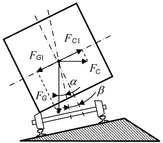
Fig. 1. Vehicle
movement with additional tilt
of the body in curve
To reduce the
effect of centrifugal force in the curves, the outer rail is placed
higher than the internal one by the value of cant h,
m. Therefore, the track is inclined with respect to the horizon at
the following angle:
 , (2)
, (2)
where
 – track width, m.
Due to this, a part of the
centrifugal force is compensated by the force of gravity, since in
the floor plane of the car the projections of the foregoing
forces are directed to the opposite sides.
Obviously,
the result
of the
vectorial
addition of
these forces
will be
some unbalanced
lateral force
 .
.
To
provide the
greatest comfort
for passengers,
the unbalanced
lateral force
should be
equal to
zero. The
projection of the centrifugal force must be fully compensated by the
gravity component:
 , (3)
, (3)
where
g –
free fall
acceleration,
m/s2.
The
profile of
the curves
is constructed
with a
fixed optimal
canting.
But since
trains move
at different
speeds, one
should define
«insufficient
canting».
The maximum
canting is
limited for
reasons of
preventing the
rolling stock
tipping into
the curve
when it
stops or
moves slowly
and is
equal to
 =0,15
m.
=0,15
m.
Insufficient
canting can be compensated by inclining the vehicle body with
the help of additional force for the angle
 ,
into such a position that the body would occupy during movement in
the curve with the required canting of the outer rail, i.e.
,
into such a position that the body would occupy during movement in
the curve with the required canting of the outer rail, i.e.
 .
.
The condition
for compensating the centrifugal force for tilting trains can be
written as follows:
 (4)
(4)
Consequently,
the expression for the additional angle of the body tilt will be as
follows:
 (5)
(5)
The
disadvantage of
this method
is that
the author
[10] does not
take into
account the
condition of
passenger
comfort on
horizontal
unbalanced
acceleration,
and the
additional angle
of the
body tilt
is determined
with full
compensation of
the centrifugal
force, i.e.
the unbalanced
acceleration in
this case
is equal
to zero,
and as
it is
known, the
permissible
unbalanced
acceleration is
 m/s2.
m/s2.
The
authors in
[6] and
[1] propose the
method for
determining the
permissible
speed of
the tilting
train in
the curve,
which is
as follows.
In
circular curves,
the permissible
speed of
movement is
determined by
the safety
criterion of
movement on
the horizontal
unbalanced
acceleration:
 (6)
(6)
where
 – estimated
canting, mm;
S – distance
between the
rail top axes,
1 600 mm.
– estimated
canting, mm;
S – distance
between the
rail top axes,
1 600 mm.
In
modern vehicles,
which during
curve passing
have the
body forced
tilt into
the middle
of the
curve at
the angle
 ,
the permissible
speed increases
with the
introduction of
canting into
the formula
(6), which is
an additional
compensation for
the unbalanced
acceleration:
,
the permissible
speed increases
with the
introduction of
canting into
the formula
(6), which is
an additional
compensation for
the unbalanced
acceleration:
 (7)
(7)
Substituting
formula (7) into
formula (6), we
obtain the
permissible
speed of
the train
with the
forced tilt
of the
body in
the curve:
 (8)
(8)
The main
disadvantage of this method is that the authors [1, 8] do not
perform calculations to determine the additional angle of the train
tilt
during the curve passage, since the additional tilt angle depends on
the curve radius, movement speed, canting and the maximum tilt angle
achieved by the rolling stock.
Purpose
Justification of the expediency
of operation of the air-cushioned rolling stock with tilt in curved
sections on the railways of Ukraine for increased speed and comfort
of passengers.
Methodology
The methodology for determining
the maximum permissible speed of the tilted train in curved
track involves the use of methods of linear and vector algebra and
empirical formulas for applied scientific and technical research.
The
calculation of the maximum speed of the tilted train in curved track
is based on the principle of calculating centrifugal force for the
velocities that meet the safety criteria of movement on the
horizontal unbalanced acceleration in the stable radius curve.
Basic material
The modern high-speed trains
have three main systems of body tilt in curves: passive, active and
active-passive.
In
passive tilt
systems, the
body is
suspended like
a pendulum
with a
centre of
rotation above
the body
gravity centre.
When moving in the curve, the centre of gravity under the action of
centrifugal force is displaced externally, providing the required
angle of the body tilt. The tilt angle of the passive system can be
up to 3°–5°. In this case, a significant part of the centrifugal
force is compensated, and the speed in the curves can be
increased by 14% [8].
In active systems, the tilt of
the body is performed with the help of special devices.
Hydraulic, pneumatic, electro-hydraulic and electromechanical
systems are used as a power-driven mechanism of the body forced
tilt. In order to ensure correct operation of the system, the
rolling stock is equipped with a number of sensors, which, depending
on the speed, curve radius and canting, determine the optimal angle
of the rolling stock tilt. Typically, the tilt angle of the active
systems is 8°–10° [8], which makes it possible to increase
the speed to 25–30 %.
The active-passive tilt system
can work both as active and passive depending on the speed and the
desired angle of the body tilt. If you need to turn the body to
3°–5° angle, then the system works as a passive one. If you need
to set a larger angle, then the system starts to work as active. The
advantage of the passive tilt system is that there is no need to
spend energy for the body tilt and it has simple and reliable
design. And the advantage of the active one is the greater maximum
possible tilt angle [5, 14].
In this
paper, the method for determining the permissible speed of movement
in the curve with the body forced tilt is as follows:
– determination
of the
permissible
speed of
the train
in the
curve provided
the passengers
feel
comfortable;
– determination
of the
forces acting
on the
train in
the track
curved section
(centrifugal
force and
gravity);
– determination
of the
permissible
centrifugal
force in
the curve
subject to
comfort;
– determination
of the
resultant force
for centrifugal
and
gravitational
forces;
– determination
of the
angle of
deflection of
the resultant
force vector
at the
permissible
speeds from
the vertical
axis Oy;
– determination
of the
angle of
deflection of
the resultant
force vector
from the
vertical axis
of the
locomotive,
which in
turn is
the desired
angle of
the body
tilt in
the curve;
– determination
of the
permissible
angle of
deflection
of the
resultant force
vector from
the vertical
axis Oy
with the
body forced
tilt;
– determination
of the
value of
the resultant
force and
centrifugal
force with
the body
forced tilt
in the
curve;
– definition
of maximum
speed with
the >maximum
angle of
the body
tilt, which
is provided
by the
rolling stock
design;
– construction
of the
graph showing
the dependence
of the
centrifugal
force of
the locomotive
on the
speed in
the track
curve, the
limitation of
the centrifugal
force without
body tilt, the
limitation of
the centrifugal
force with
body tilt
and the
limitation of
the speed
at the
maximum angle
of the
body tilt.
Increasing
the speed
of movement
requires much
greater
compliance with
traffic safety
criteria.
This is especially true for the tilting
rolling stock. In world practice, the following traffic safety
criteria are used:
– vertical
acceleration,
which arises
during the
movement of
the train
in the
curve section
of the
longitudinal
track profile;
– longitudinal
acceleration
associated with
the processes
of braking
and run-up;
– horizontal
unbalanced
acceleration,
which arises
during the
movement in
the track
curve in
plan;
– full
acceleration, acting on the passenger;
– vertical
acceleration
occurring in
the passenger
car body,
caused by
fluctuations,
and acting
on a
passenger;
– criterion
of safety of movement on elastic edging of a rail.
The criterion that influences
the safety of the passengers of the tilting train the most is the
criterion of comfort, that is, the criterion of safety of movement
on the horizontal unbalanced acceleration.
As
already noted,
the permissible
speed of
movement in
the track
curve in
the condition
of comfort
of passengers
and locomotive
crew is
determined
by the
largest value
of unbalanced
acceleration
m/s2,
which is
specified on
the railways
of the
CIS countries.
In justified cases, in order to eliminate
the speed limit on individual curves depending on the locomotive
type, the transverse permissible unbalanced acceleration can be
increased to 1 m/s2,
but not long-term and not repeated. Permissible unbalanced
acceleration for freight trains, provided that the outer or inner
rail of the curve is not overloaded, is equal to ± 0.3 m/s2
[3, 12].
Different authors offer
different formulas for determining the permissible speed of movement
in the curved track. From the considerable volume of literature, it
is possible to define three most used empirical formulas for
determining the permissible speed of passage of curves provided the
comfort of passengers and locomotive crew. Formula (9) is given in
[3], formula (10) in [11], and formula (11) in [2].
 (9)
(9)
 (10)
(10)
 (11)
(11)
According to
the above formulas in Fig. 2 we constructed the graph of dependence
of the permissible movement speed on the curve radius without body
tilt for the following conditions: the canting

 and
and
 mm, the curve radius
 m. Since the
difference in the results obtained by formulas (9), (10) and (11) is
less than one per cent, so it makes no sense to construct all three
dependencies; it’s enough to just construct the dependence by one
of the formulas for three different cants.
m. Since the
difference in the results obtained by formulas (9), (10) and (11) is
less than one per cent, so it makes no sense to construct all three
dependencies; it’s enough to just construct the dependence by one
of the formulas for three different cants.
The vehicle moving in a curve,
in general, is affected by two main forces: gravity and
centrifugal force, which depends on the speed and radius of the
curve. All forces acting on the locomotive in the curve are
shown in Fig. 3. The result of the vector addition of centrifugal
and gravitational forces is the resultant force.
For
the calculation
scheme of
the forces
acting, the
centrifugal
force
 ,
acting on the rolling stock in the curve
is determined by the formula (1), and the angle of canting
,
acting on the rolling stock in the curve
is determined by the formula (1), and the angle of canting
 is determined by the formula (2).
Substituting in formula (1) the
value of the maximum permissible speed under the condition of
comfort, which is calculated by the formula (9), we obtain the
maximum permissible centrifugal force acting on the rolling stock in
the curved track.
The fig. 4 shows the graph of
dependence of the centrifugal force on the curve radius at
different speeds.
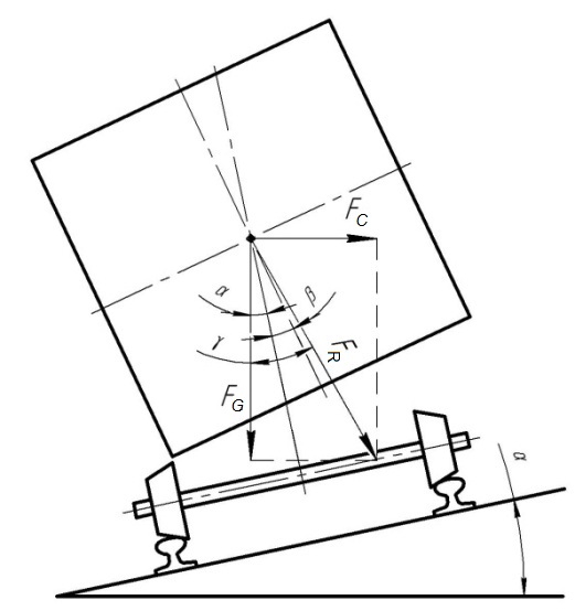
Fig. 3. Vehicle
movement without body tilt
in the curve:
 –
gravity
force;
–
centrifugal
force;
–
gravity
force;
–
centrifugal
force;
 –
resultant force of gravity and centrifugal forces;
–
resultant force of gravity and centrifugal forces;
–
angle
between
the
vector
of
the
gravity
force
and
the
vertical
axis
of
the
rolling
stock
without
body
tilt
and
the
angle
of
canting;
–additional
angle
of
rolling
stock
tilt;
–
angle
between
the
resultant
force
vector
and
the
gravity
force
vector
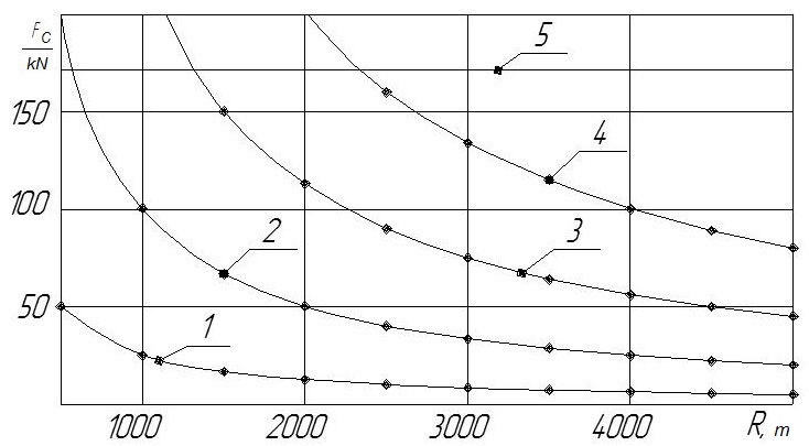
Fig. 4. Graph of
dependence of the centrifugal force
on the curve radius at
different speeds:
1,
2, 3, 4
– functions
 at speeds of 50,
100, 150 and 200 km/h respectively;
at speeds of 50,
100, 150 and 200 km/h respectively;
5
– limitation
of
centrifugal
force
The
resultant force
from the
centrifugal and
gravitational
forces is
determined by
the vector
addition and
will be
equal to:
 (12)
(12)
The force of gravity acting on
the rolling stock is determined by:
 (13)
(13)
The basis of the method for
determining the permissible speed of the tilting rolling stock is
the definition of the maximum deflection angle of the resultant
vector without and with body tilt, provided that the passengers
feel comfortable. The deflection angle of the resultant vector
without body tilt is equal to:
 (14)
(14)
For
the greatest
comfort of
the passengers,
the resultant
vector should
be perpendicular
to the
floor plane.
Besides, this angle is an additional
necessary angle for the body tilt in the curve and is determined by
the formula:
 . (15)
After the
substitution and transformation of formulas (14) and (15) we obtain:
 . (16)
 . (17)
It is seen that the formula for
determining the additional angle of body tilt (17) coincided with
the formula (5), which is calculated according to the method [1].
If
we calculate
the additional
tilt angle
by the
formula (15), it
is worth
noting that
the additional
tilt angle
can be
not only
positive, but
also negative.
The negative tilt angle is formed when the
body is tilted in the direction opposite to the turn. This is
necessary in the case when the train moves at a low speed in the
curve with a sufficiently high canting.
The
permissible tilt angle of the resultant vector to the vertical axis
Oy with
the body forced tilt is defined as the sum of the deflection angles
of the resultant vector without body tilt and the required
additional tilt angle:
 . (18)
Now,
the permissible
resultant and
centrifugal
forces with
the body
forced tilt
will equal
respectively:
 . (19)
 . (20)
In
order to
determine the
maximum
permissible
speed of
the tilting
train under
the condition
of maximum
compensation of
centrifugal
force and
subject to
the horizontal
unbalanced
acceleration, it
is necessary
to solve
the equation
(17) in relation
to the
unknown velocity
V, taking
the tilt
angle ,
since this
tilt angle
is the
maximum
permissible for
this type
of rolling
stock.
,
since this
tilt angle
is the
maximum
permissible for
this type
of rolling
stock.
The
maximum speed
of the
tilting
locomotive,
provided that
the resultant
force is
perpendicular to
the car
floor, is
determined as:
 . (21)
The
maximum speed
of the
tilting
locomotive,
provided that
the resultant
force has
the maximum
allowable tilt
angle with
the condition
of comfort,
will be
determined by
the formula:
 . (22)
Findings
The
Figure 5 shows
the constructed
graph for
determining the
permissible
speed of
tilting train movement
in the
curve.
The graph
shows the
centrifugal
force acting
on the
rolling stock
when speed
increases and
a number
of limitations:
curve 1 is
the permissible
centrifugal
force without
body tilt, curve
2 is the
permissible
centrifugal
force with
body tilt, curve
3 is the
function
 of centrifugal
force from
the speed
acting on
the train
in the
curve, curve
4 is the maximum
speed limitation
provided that
the resultant
vector is
perpendicular to
the body
floor, curve
5 is the
maximum speed
limitation with
body tilt under
the condition of passenger
comfort. The
graph is
constructed for
the following
input data:
train speed
of centrifugal
force from
the speed
acting on
the train
in the
curve, curve
4 is the maximum
speed limitation
provided that
the resultant
vector is
perpendicular to
the body
floor, curve
5 is the
maximum speed
limitation with
body tilt under
the condition of passenger
comfort. The
graph is
constructed for
the following
input data:
train speed
 km/h,
curve radius
km/h,
curve radius
 m, canting
mm,
maximum angle
of rolling
stock tilt
.
For comparison, Table 1 shows the results
of calculations of the permissible speed of tilting train in the
track curve according to the authors’ methods [1, 6, 10] and the
calculation method presented in this article.
m, canting
mm,
maximum angle
of rolling
stock tilt
.
For comparison, Table 1 shows the results
of calculations of the permissible speed of tilting train in the
track curve according to the authors’ methods [1, 6, 10] and the
calculation method presented in this article.
As
the graph shows, the maximum permissible speed of the train without
body tilt is 132 km/h, and with body tilt – 189 km/h. The
velocity
gain
in
the
curve
m
is
30
%.
This
result can be considered adequate, as it coincides with the results
of calculations [1, 6].
Similar
dependences
can
be
constructed
for
other
values
of
curves
radii
and
canting.
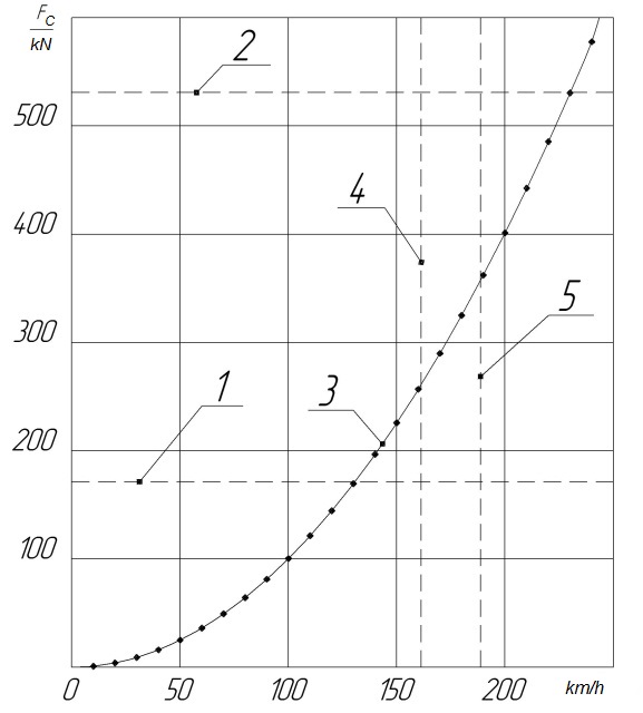
Fig. 5. Graph for
determining the permissible speed
of tilting train movement in
the curve
Table
1
Results of
calculations of the permissible train speed according to different
methods
|
Method
of calculating the permissible train speed in the curve
|
Speed
of the
train without
body tilt,
km/h
|
Speed
of the
train
provided that
the
centrifugal
force is
fully
compensated
by body
tilt,
km
/ h
|
Speed
of the
train with
body tilt
under
comfortable
conditions,
km / h
|
|
Methodology
described in the article
|
130.7
|
161.4
|
188.7
|
|
Methodology of
the authors
[1,
6]
|
130.6
|
–
|
186.3
|
|
Methodology
of the author [5]
|
–
|
161.4
|
–
|
Originality and practical
value
The method
for determining the permissible speed of movement and the additional
angle of body tilt in the track curve of the tilting train is
improved. It takes into account the comfort
condition by the value of the horizontal unbalanced acceleration.
This will allow more accurately determining the speed of movement of
this type of rolling stock in the curved track section.
Conclusions
1. As
demonstrated by the calculations made, the determining factors for
the railways of Ukraine affecting the train speed are the curve
radii and canting, which is designed for the movement of freight
trains.
2. The
results of
calculations
indicate that
the maximum
permissible
speed of
the train
without body
tilt in
the curve
m is
132 km/h,
and with
body tilt
– 189 km/h.
The velocity
gain is
57 km/h.
3. Having
analyzed all the factors affecting the movement speed and the
obtained calculation results, it can be concluded that this type
of rolling stock is expedient to be used on the railways of Ukraine.
This is due to the fact that in Ukraine there are many curves of
small radius that are inappropriate and to some extent
impossible to increase.
4. Besides,
due to more uniform maintenance of high-speed train driving, it is
possible to achieve energy saving [4].
5. Putting
into operation of the tilting rolling stock on the Ukrainian
railways will allow getting the velocity gain of up to 30 % in the
curve and up to 10 % in the section (depending on the number of
curves). Increased speed of trains will considerably strengthen the
position of railways in the transport system of Ukraine.
LIST OF REFERENCE LINKS
Аналіз
можливості застосування в Україні
рухомого складу з примусовим нахилом
кузова вагонів при організації
швидкісного руху / А. П. Зубко, І.
П. Корженевич,
М. Б. Курган, Д. М.
Курган // Вісн. Дніпропетр.
нац. ун-ту залізн. трансп. ім. акад. В.
Лазаряна. – Дніпропетровськ, 2004. –
Вип. 4. – С. 156–164.
Білий,
В. І. Залізнична колія : навч. посіб. /
В. І. Білий. – Донецьк,
2007. – 160 с.
Боднар,
Б. Є. Теорія та конструкція локомотивів.
Екіпажна частина : підруч. / Б. Є. Боднар,
Є. Г. Нечаєв,
Д. В. Бобир. – Дніпропетровськ : Ліра
ЛТД, 2009. – 284 с.
Визначення
енергозаощаджуючих режимів розгону
поїздів / Б. Є. Боднар, М. І. Капіца, А. М.
Афанасов, Д. М. Кислий // Наука та прогрес
транспорту. – 2015. – № 5 (59). – С. 40–52.
doi:
10.15802/stp2015/55359.
Єріцян,
Б. Х. Моделювання комбінованої системи
нахилу кузову швидкісного рухомого
складу залізничного транспорту / Б. Х.
Єріцян, Б. Г. Любарський, Д. І. Якунін //
Вост.-Европ. журн. передовых технологий.
– 2016. – № 2 (9). – С. 4–17. doi:
10.15587/1729-4061.2016.66782.
Курган,
М. Б. Організація швидкісного руху при
застосуванні рухомого складу з
примусовим нахилом кузова вагонів /
М. Б. Курган, І. П. Корженевич, В.
В. Арсонов
// Вісн. Дніпропетр. нац. ун-ту залізн.
трансп. ім. акад. В. Лазаряна. –
Дніпропетровськ, 2006. – Вип. 11. – С.
50–59.
Курган,
Н. Б. Предпосылки создания высокоскоростных
магистралей в Украине / Н. Б. Курган //
Українські залізниці. – 2015. – № 5/6
(23/24). – С.
16–21.
Ковалев,
В. И. Скоростной и высокоскоростной
железнодорожный транспорт / В. И.
Ковалев. – Санкт-Петербург : Искусство
России, 2001. – Т. 2. – 350 с.
Правила
визначення підвищення зовнішньої
рейки і встановлення допустимих
швидкостей в кривих ділянках колії. –
Дніпропетровськ : Арт-Прес, 1999. –
44 с.
Редченко,
Е. С. Определение величины и распределение
центробежной силы для проведений
испытаний поездов с наклоняемыми
кузовами на катковом стенде / Е. С.
Редченко // Локомотив-информ. – 2008. –
№ 5. – С. 12–17.
Сокол,
Э. Н. Сходы с рельсов и
столкновения подвижного состава
(Судебная экспертиза. Элементы теории
и практики) : монография / Э. Н. Сокол. –
2-е изд., перераб. и доп. – Киев : Транспорт
Украины, 2004. – 368 с.
On
Influence of Design Parameters Of Mining Rail Transport On Safety
Indicators [Electronic resource] /
K.
Ziborov,
V.
Protsiv,
S.
Fedoriachenko,
I.
Verner
// Mechanics,
Materials Science & Engineering J. – 2016.
– Vol. 2 (1). – P. 63–70. –
Available
at:
http://mmse.xyz/en/on-influence-of-design-parameters-of-mining-rail-transport-on-safety-indicators/.
– Title from thr screen. – Accessed
: 19.06.2017.
Qi,
Z. A three-dimensional coupled dynamics model of the air spring of
a high-speed electric multiple unit train / Z. Qi, F. Li, D. Yu //
Proc.
of the Institution of Mechanical Engineers. Part F : J. of Rail and
Rapid Transit. – 2017. – Vol. 231.
– Iss. 1. – P. 3–18. doi: 10.1177/0954409715620534.
Zhou,
R.
Robust
system
state
estimation
for
active
suspension
control
in
high-speed
tilting
trains
/
R.
Zhou,
A.
Zolotas,
R.
Goodall
// Vehicle
System
Dynamics.
– 2014. – Vol.
52.
– Iss.
sup1.
– P.
355–369. doi:
10.1080/00423114.2014.901540.
М.
І. КАПІЦА1,
Д. В. БОБИРЬ2,
А. Є. ДЕСЯК3*
1Каф.
«Локомотиви», Дніпропетровський
національний університет залізничного
транспорту імені академіка
В. Лазаряна,
вул. Лазаряна, 2, Дніпро, Україна, 49010,
тел. +38 (0562) 33 19 61, ел. пошта m.i.kapitca@ua.fm,
ORCID 0000-0002-3800-2920
2Каф. «Локомотиви»,
Дніпропетровський національний
університет залізничного транспорту
імені академіка
В. Лазаряна, вул.
Лазаряна, 2, Дніпро, Україна, 49010, тел.
+38 (0562) 33 19 61, ел. пошта dmitrob@ua.fm,
ORCID 0000-0003-1441-3861
3*Каф.
«Локомотиви», Дніпропетровський
національний університет залізничного
транспорту імені академіка
В. Лазаряна,
вул. Лазаряна, 2, Дніпро, Україна, 49010,
тел. +38 (0562) 33 19 61, ел. пошта
andrey.desyak1992@gmail.com,
ORCID 0000-0001-8650-5242
ВИЗНАЧЕННЯ
ДОПУСТИМОЇ ШВИДКОСТІ РУХУ ПОЇЗДА
З
ПРИМУСОВИМ НАХИЛОМ КУЗОВА в КРИВИХ
ДІЛЯНКАХ КОЛІЇ
Мета.
Головною метою статті
є визначення допустимої швидкості руху
поїзда на пневматичному підвішуванні
з примусовим нахилом кузова в кривій
ділянці колії та обґрунтування
доцільності експлуатації даного типу
рухомого складу на залізницях України.
Це необхідно для збільшення швидкості
руху, підвищення комфорту пасажирів
та економії енергоресурсів за рахунок
більш рівномірного швидкісного режиму
ведення поїзда. Методика.
Визначення максимальної
допустимої швидкості руху поїзда в
кривій з примусовим нахилом кузова
передбачає застосування методів
лінійної, векторної алгебри та емпіричних
формул для прикладних науково-технічних
досліджень. В основі розрахунку
максимальної швидкості руху закладений
принцип розрахунку відцентрової сили
для швидкостей руху, які відповідають
критеріям безпеки руху по горизонтальному
незагашеному прискоренню в кривій
сталого радіуса. Результати.
Отримані розрахунки
показали, що в кривій ділянці колії
радіусом 1 000 м, за умови
комфортабельності пасажирів, максимальна
допустима швидкість руху поїзда без
примусового нахилу кузова складає 132
км/год, а з примусовим нахилом кузова
– 189 км/год. Приріст швидкості в кривій
дорівнює близько 30 %, та до 10 % – на
ділянці (в залежності від кількості
кривих). Наукова новизна.
Авторами удосконалено метод визначення
допустимої швидкості поїзда з примусовим
нахилом кузова в кривій. Він полягає у
визначенні допустимої відцентрової
сили, яка діє на поїзд у кривій сталого
радіуса з урахування умов комфортабельності
пасажирів. Практична
значимість. Даний метод
дозволяє досить точно визначити
допустиму швидкість руху (за умови
комфортабельності пасажирів) у кривій
ділянці та необхідний додатковий кут
нахилу поїзда в залежності від швидкості,
радіуса кривої та підвищення зовнішньої
рейки. Збільшення швидкості руху та
комфорту пасажирських поїздів у
майбутньому призведе до збільшення
попиту на послуги залізничного транспорту
серед населення та зміцнення позицій
залізничного транспорту в транспортній
системі України.
Ключові
слова: високошвидкісний транспорт;
рухомий склад; система нахилу кузова;
відцентрова сила; рівнодіюча сила;
радіус кривої; підвищення зовнішньої
рейки
М.
И. КАПИЦА1,
Д. В. БОБЫРЬ2,
А. Е. ДЕСЯК3*
1Каф.
«Локомотивы», Днепропетровский
национальный университет железнодорожного
транспорта имени академика
В. Лазаряна,
ул. Лазаряна, 2, Днипро, Украина, 49010, тел.
+38 (0562) 33 19 61, эл. почта m.i.kapitca@ua.fm,
ORCID
0000-0002-3800-2920
2Каф.
«Локомотивы», Днепропетровский
национальный университет железнодорожного
транспорта имени академика
В. Лазаряна,
ул. Лазаряна, 2, Днипро, Украина, 49010, тел.
+38 (0562) 33 19 61, эл. почта dmitrob@ua.fm,
ORCID
0000-0003-1441-3861
3*Каф.
«Локомотивы», Днепропетровский
национальный университет железнодорожного
транспорта имени академика В. Лазаряна,
ул. Лазаряна, 2, Днипро, Украина, 49010, тел.
+38 (0562) 33 19 61,
эл. почта andrey.desyak1992@gmail.com,
ORCID 0000-0001-8650-5242
ОПРЕДЕЛЕНИЕ
ДОПУСТИМОЙ СКОРОСТИ ДВИЖЕНИЯ ПОЕЗДА
С ПРИНУДИТЕЛЬНЫМ НАКЛОНОМ КУЗОВА в
КРИВЫХ УЧАСТКАХ ПУТИ
Цель.
Главной целью статьи
является определение допустимой
скорости движения поезда на пневматической
подвеске с принудительным наклоном
кузова в кривом участке
пути и обоснование целесообразности
эксплуатации данного типа подвижного
состава на железных дорогах Украины
для увеличения скорости движения,
повышения комфорта пассажиров и экономии
энергоресурсов за счет более равномерного
скоростного режима ведения поезда.
Методика. Определение максимальной
допустимой скорости движения поезда
в кривой с принудительным наклоном
кузова предусматривает применение
методов линейной, векторной алгебры и
эмпирических формул для прикладных
научно-технических исследований. В
основе расчета максимальной скорости
движения заложен принцип расчета
центробежной силы для скоростей
движения, которые соответствуют
критериям безопасности движения по
горизонтальному непотушенному
ускорению в кривой постоянного радиуса.
Результаты. Полученные расчеты
показали, что в кривом участке пути
радиусом 1 000 м, при условии
комфортабельности пассажиров,
максимальная допустимая скорость
движения поезда без принудительного
наклона кузова составляет 132 км/ч, а с
принудительным наклоном кузова – 189
км/ч. Прирост скорости в кривой составляет
около 30 %, и до 10 % – на участке (в
зависимости от количества кривых).
Научная новизна. Усовершенствован
метод определения допустимой скорости
поезда с принудительным наклоном
кузова в кривой, который заключается
в определении допустимой центробежной
силы, действующей на поезд в кривой
постоянного радиуса с учетом
условий комфортабельности пассажиров.
Практическая значимость. Данный
метод позволяет достаточно точно
определить допустимую скорость движения
(по условию комфортабельности пассажиров)
в кривой и необходимый дополнительный
угол наклона поезда в зависимости от
скорости, радиуса кривой и возвышения
наружного рельса. Увеличение скорости
движения и комфорта пассажирских
поездов в будущем приведет к увеличению
спроса на услуги железнодорожного
транспорта среди населения и укрепит
позиции железнодорожного транспорта
в транспортной системе Украины.
Ключевые
слова: высокоскоростной транспорт;
подвижной состав; система наклона
кузова; центробежная сила; равнодействующая
сила; радиус кривой; возвышения наружного
рельса
REFERENCES
Zubko,
A. P., Korzhenevych, I. P., Kurhan, M. B., & Kurhan, D. M.
(2004). The
analysis of possibility of application in ukraine of the rolling
stock with tilting body cars when organizing high-speed traffic.
Bulletin of Dnipropetrovsk National
University of Railway Transport, 4,
156-164.
Bilyi,
V. I. (2007). Zaliznychna koliia
[Tutorial]. Donetsk: Donetsk Railway Transport Institute.
Bodnar,
B. Y., Nechaiev, Y. H., & Bobyr, D. V. (2009). Teoriia
ta konstruktsiia lokomotyviv. Ekipazhna chastyna
[Manual]. Dnipropetrovsk: PP «Lira LTD».
Bodnar,
B. Y., Kapitsa, M. I., Afanasov, A. M., & Kyslyi, D. N. (2015).
Definition of energy saving acceleration modes of trains. Science
and Transport Progress, 5
(59), 40-52. doi:
10.15802/stp2015/55359
Yeritsyan,
B., Liubarskyi, B., & Iakunin, D. (2016). Simulation of
combined body tilt system of high-speed railway rolling stock.
Eastern-European Journal of Enterprise
Technologies, 2
(9) (80), 4-17. doi:10.15587/1729-4061.2016.66782
Kurhan,
M. B., Korzhenevych, I. P., & Arsonov, V. V. (2006).
Organization of high-speed traffic with the use of rolling stock
with a forced tilt body cars. Bulletin
of Dnipropetrovsk National University of Railway Transport,
11,
50-59.
Kurhan,
M. B. (2015). Predposylki sozdaniya vysokoskorostnykh magistraley v
Ukraine. Ukrainian Railways,
5-6
(23-24), 16-21.
Kovalev,
V. I. (2001). Skorostnoy i
visokoskorostnoy zheleznodorizhnyy transport
(Vol. 2). Saint Petersburg.
Ukrzaliznytsia.
(1999). Pravyla vyznachennia
pidvyshchennia zovnishnoi reiky i vstanovlennia dopustymykh
shvydkostei v kryvykh diliankakh kolii.
Dnipropetrovsk: Art-Pres.
Redchenko,
Y. S. (2008). Opredeleniye velichiny i raspredeleniye
tsentrobezhnoy sily dlya provedeniy ispytaniy poyezdov s
naklonyaemymi kuzovami na katkovom stende. Lokomotyv-Inform,
5,
12-17.
Sokol,
E. N. (2004). Skhodi s relsov i
stolknoveniya podvizhnogo sostava (Sudebnaya ekspertiza. Elementy
teorii i praktiki) [Monograph] (2nd
ed.). Kyiv: Transport Ukrainy.
Ziborov,
K., Protsiv, V., Fedoriachenko, S., & Verner, I. (2016). On
Influence of Design Parameters of Mining Rail Transport on Safety
Indicators. Mechanics, Materials
Science & Engineering, 2
(1), 63-70. Retrieved from
http://mmse.xyz/en/on-influence-of-design-parameters-of-mining-rail-transport-on-safety-indicators/
Qi,
Z., Li, F., & Yu., D. (2017).
A three-dimensional coupled dynamics model of the air spring of a
high-speed electric multiple unit train. Proceedings
of the Institution of Mechanical Engineers, Part F: Journal of Rail
and Rapid Transit, 231
(1), 3-18.
Zhou,
R., Zolotas, A., & Goodall, R. (2014). Robust system state
estimation for active suspension control in high-speed tilting
trains. Vehicle System Dynamics,
52 (1),
355-369. doi:10.1080/00423114.2014.901540
Prof. V. L. Gorobets, D. Sc.
(Tech.), (Ukraine); Prof. A. V. Sokhatskyi, D. Sc. (Tech.),
(Ukraine) recommended this article to be published
Received:
March 31,
2017
Accessed:
July 05, 2017
doi
10.15802/stp2017/109537 ©
M. I. Kapitsa, D. V. Bobyr, A. Y. Desiak, 2017