ISSN 2307–3489 (Print), ІSSN
2307–6666 (Online)
Наука та прогрес
транспорту. Вісник Дніпропетровського
національного університету залізничного
транспорту, 2017, № 4 (70)
автоматизовані
системи управління на транспорті
автоматизовані
системи управління
на транспорті
UDC
656.256.3:621.316.91
K. I. yashchuk1*
1*Dep.
«Automation, Remote Control and Communication», Dnipropetrovsk
National University of Railway Transport
named after Academician
V. Lazaryan, Lazaryan St., 2, Dnipro, Ukraine, 49010, tel. +38 (066)
647 54 89,
e-mail k.i.yaschuk@gmail.com,
ORCID 0000-0002-8606-5790
POTENTIALS RAILWISE
PROPAGATION STUDY
Purpose. The article deals with conducting the
study of the potentials and currents propagation along the rails to
evaluate the potential difference and the current asymmetry in the
rails that may have an impact on the work of railway automatics and
supervisory systems. Methodology. To compass the purpose, the
author applies methods of analysis and synthesis of track circuit
electrical engineering calculations, mathematical modeling and
methods of homogeneous and heterogeneous ladder circuits. Findings.
The conducted
theoretical studies
indicate that in
the mountainous
sections of DC
traction railways
there are
very high-level
currents, whereby
even at nominal
asymmetry ratio the
asymmetry current
will be unacceptably
high. The
re-equipment of running line with the automatic blocking system with
tonal rail circuits resulted in reduction of the number of impedance
bonds, the equalizing functions of which required further advanced
research, that allowed obtaining the potential railwise propagation
curves when installing the impedance bonds every 6 and 5 km. The
resulting potential difference was too high for railway automation
systems, so the potential propagation study was conducted with
impedance bonds placed every 3 and 3.5 km, which greatly improved
the operation conditions of track circuits. Originality.
The proposed method for calculating the propagation of
potentials and currents in the rail network of DC traction line is
characterized by the representation of the common ladder circuit of
each rail as a series of T-shaped four-poles connected in cascade,
taking into account the grounding of the contact-line supports on the
nearer rail. It has allowed estimating the levels of asymmetry
currents that branch into the equipment of track circuits and have a
negative impact on their operation. Practical
value.
The obtained
results can be used in designing and re-equipping the running lines
with new railway automatics and supervisory systems, as well as for
evaluating the influence of high asymmetry currents on the railway
automation systems operation.
Keywords: traction
currents; track circuits; impedance bond; asymmetry current;
potentials propagation
Introduction
Traction current has a
significant impact on the operation of automatic block systems (AB)
[1]. There are rail sections where it reaches very high levels,
resulting in melting of track choke cables. Such are the mountain
sections of railways with electric drive of direct current. In this
way, the problem of railwise propagation of potentials caused by
traction current becomes actual, the study of which will allow to
estimate the difference between the derived potentials and the
negative impact on the equipment of the track circuits (TC), in
particular, the tonal ones (TTC).
Purpose
The purpose
of the work is to study the propagation of potentials along the
rails in order to evaluate the impact of traction current on TTC
operation. This
will enable us to take a number of necessary technical measures to
combat asymmetry, as well as to investigate their effectiveness in
advance.
Methodology
As noted,
high levels of traction currents are peculiar for mountain railways.
This can be explained by the presence of steep climbs, to overcome
which the locomotive requires large traction effort, provided by 2-3
electric locomotives. The work examined the mountainous section with
DC electric traction of Lavochne – Beskid – Skotarskoye of Lviv
Railways. As a result of the carried out researches it was
established that traction currents reach 7000 A on this site and
it is
expedient to
re-equip
the section
AB with
50 Hz frequency
TC onto
the ABTK
system, which
uses TTC
without
isolating joints
[2], resulting in reduced
number of
impedance bonds
(IB),
as in fact,
in the
case of
TTC, they
are installed
only for
the potential
alignment in
the rails,
while the
IBs pass
less current.
This greatly
facilitates the
operation of
the track
circuits on
the running
line because
the impedance
bond is a
weak point
in the
TC, especially
in the
presence of
large traction
currents [3].
If
we take
into account
such an
important
parameter as
the asymmetry
ratio, then
its limiting
value according
to the
technical
conditions is
equal to
 .
In this case, the difference in rail
currents will be equal to
.
In this case, the difference in rail
currents will be equal to
 .
In practice, the asymmetry ratio can reach
0.2. As a result of the high traction currents flow, normal
operation of IBs is violated due to their inadmissible heating and
magnetization [4]. As a result of thermal overheating, IB may even
break down. The common occurrence is the IB core saturation,
resulting in a decrease in the IB input impedance to signal current,
which may lead to the voltage reduction on the track receiver up to
the voltage value of non-attraction of relay armature. Consequently,
the asymmetry current increase can cause a parametric failure of the
TC.
.
In practice, the asymmetry ratio can reach
0.2. As a result of the high traction currents flow, normal
operation of IBs is violated due to their inadmissible heating and
magnetization [4]. As a result of thermal overheating, IB may even
break down. The common occurrence is the IB core saturation,
resulting in a decrease in the IB input impedance to signal current,
which may lead to the voltage reduction on the track receiver up to
the voltage value of non-attraction of relay armature. Consequently,
the asymmetry current increase can cause a parametric failure of the
TC.
Since the
rails are not isolated, part of the reverse traction current flows
through the ground. This fact has a significant impact on a number
of phenomena, in particular, the traction network resistance and TC
operation [5].
The earth leakage current from rails
depends on the potential difference between the rails and the ground
and the resistance of the circuit through which this current flows.
The circuit consists of two consecutive parts. The first part is the
resistance of the transition point of the current from the rails to
the sleepers and ballast; the second part is the resistance of the
ground itself on the path of leakage current.
For the
analysis of the spread of traction current along the rails,
regardless of the train situation and the section complexity, it is
necessary to determine the load of the substations [6]. To
simplify the
calculation, we
can accept
some assumptions
that will
not make
a tangible
error.
With good insulation of rails from the ground in the absence of
earth leakage, the train loads can be distributed between
substations in the usual way – inversely proportional to distances
to the neighbouring substations (with constant area of the section
of the overhead wires and the same voltage of traction substations).
If the transition resistance from the rails to the ground will be
minimal, then a significant part of the current will flow on the
ground and, in the distribution of loads between the substations,
one can neglect the resistance of the earth return [7] (rails
shunted to earth), since it is much less than the resistance of the
overhead wires. The latter
will mostly
determine the
current
distribution. It
can be assumed that wandering currents do not significantly affect
the current distribution between substations
[8].
Before
carrying out the research it is necessary to determine the load of
the traction substations [9]. The current of the first substation
–
 ,
the second one –
,
the second one –
 ,
the current of the locomotive
–
,
the current of the locomotive
–
 .
The distances
from the
substation to
the locomotive
are known.
Then the load of the traction substations (their currents) can be
found, based on the distances from the locomotive to each of the
substations. Thus, the traction current of the first substation is
determined by:
.
The distances
from the
substation to
the locomotive
are known.
Then the load of the traction substations (their currents) can be
found, based on the distances from the locomotive to each of the
substations. Thus, the traction current of the first substation is
determined by:
 .
Traction current of the second substation:
.
Traction current of the second substation:
 .
.
Once
the load
of all
substations has
been determined,
we can
go to
the calculation
circuit. In the calculations the following
resistances play a great role:
 – resistance of 1 km of track, Ohm∙km;
 – transient resistance from rails to
earth at a length of 1 km, Ohm/km;
– transient resistance from rails to
earth at a length of 1 km, Ohm/km;
 – earth resistance.
If
the resistances
and
are constant
over the
entire length,
then we
obtain a
circuit with
constant
parameters, that
is, a
circuit line.
When calculating such circuits, the
superposition method can be used. In this case, a complex contour
containing several substations and loads can be replaced with a
number of contours, in each of which flows a certain current. The
calculation circuit contains one load when the earthing connector is
infinitely distant. At the same time, all loads are considered in
turn, taking into account the currents of substations.
The basis
for analytical study of the distribution of constant voltages and
currents along the rail line (RL), which is an electric long line,
are differential equations of the Helmholtz type [10]. At the line
input there is a source of reverse traction current leakage,
herewith the expressions for the distribution of voltage and current
along the line have the form,
 ,
,
 .
Solutions of these equations lead to the
following equations:
.
Solutions of these equations lead to the
following equations:
 ,
,
 , (1)
, (1)
Where
 ,
(
,
( );
);
 – RL
propagation
coefficient at
constant
current;
– RL
propagation
coefficient at
constant
current;
 – specific rail resistance
(
– specific rail resistance
( )
and isolation conductivity (
)
and isolation conductivity ( )
of element of the line
)
of element of the line
 .
.
Each
track is
replaced by
two two-wire
homogeneous
ladder circuits
(HLC)
«rail-earth»
[11] and is presented by T-shaped
four-poles sequentially connected in a cascade (Fig. 1). The
estimated area of the RL can be taken of any length, we
conditionally take l=3 km, it will contain N=6 identical segments of
the line of 0.5 km (the quantization scale can be varied, it is
determined by the line simulation accuracy).
If
we neglect the resistance of IB to direct current, then both of the
HLCs of the line «rail – earth» are shorted, providing alignment
of the potentials of both rails with each other.
During
circuit design it is taken into account that the parameters of the
equivalent network (СЗ
EN) of the lines can vary widely, and with the relatively low
isolation resistance, the input/output resistance of HLC 1, 2 are
equal to characteristic ones. Then, the traction current load of
each line at the boundary of the block sections is the resistance of
the IB half-coils ( ),
indicating the operation of each of these HLC lines in the
short-circuit mode (SC).
),
indicating the operation of each of these HLC lines in the
short-circuit mode (SC).
General
solutions for equation (1) can be written for a symmetric four-pole
in x
coordinate system and in A-parameters. We consider the voltage
 and current
at HLC input (
and current
at HLC input ( )
as given. Then the equation of the four-pole for the entire circuit
can be written as follows:
)
as given. Then the equation of the four-pole for the entire circuit
can be written as follows:
 (2)
(2)
The equations (2) correspond to
the equations of symmetrical four-poles in A-parameters, if adopted:
For one link HLC can be
recorded
Whence
 – transfer
constant
(weakening) of
the link
(in long
lines it
is the
analogue of
– transfer
constant
(weakening) of
the link
(in long
lines it
is the
analogue of
 ),
herewith
),
herewith
 – voltage
and current
at the
input of
– voltage
and current
at the
input of
 -th
link;
-th
link;
 – voltage and
current at
the input
of
– voltage and
current at
the input
of
 -th
link;
-th
link;
 – characteristic resistance of the line.
Permanent
transfer of
the entire
HLC is
characterized by
the ratio
of voltages
at the
beginning and
at the
end of
the HLC:
 ,
,
where
 – voltage at the input of the link N,
counting from end to start;
– voltage at the input of the link N,
counting from end to start;
 – voltage at
the input of the link
,
counting from end to start.
– voltage at
the input of the link
,
counting from end to start.
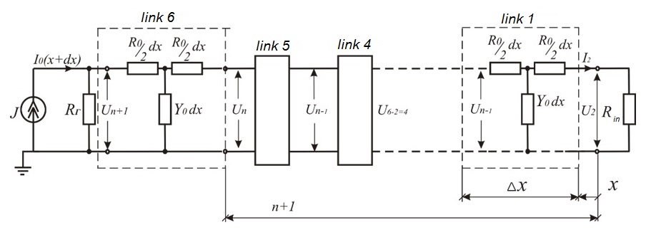
Fig.
1. Homogeneous circuit «rail-earth» with T-links
Consequently,
the transfer
constant
 .
The calculated
parameters of
the T-shaped
circuit
«rail-earth»
of the
HLC-1 track
are
.
The calculated
parameters of
the T-shaped
circuit
«rail-earth»
of the
HLC-1 track
are
 and
and
 .
The resistance
of the
rail loop
to direct
current is
.
The resistance
of the
rail loop
to direct
current is
 (with copper
rail bonds
or steel
duplicated ones)
then the
resistance of
one rail
is
(with copper
rail bonds
or steel
duplicated ones)
then the
resistance of
one rail
is .
Herewith, the resistance of the rail of
the (butting) link track consists of two components. As the practice
of operation shows, both of these components are random variables
and depend on a number of random factors such as ambient
temperature, specific resistance of the steel, bond resistance,
which depends on the quality of weld, the number of torn wire ropes,
etc. The calculations adopt the regulatory values of the parameter
.
The rail insulation conductivity
is also a parameter that depends on many
random factors: ballast material (crushed stone, sand), type of
sleepers and term of their operation, humidity and ambient
temperature, foreign impurities clogging the ballast section
(mineral salts, coal, etc.). The operation experience shows that
can vary from 10 to
.
Herewith, the resistance of the rail of
the (butting) link track consists of two components. As the practice
of operation shows, both of these components are random variables
and depend on a number of random factors such as ambient
temperature, specific resistance of the steel, bond resistance,
which depends on the quality of weld, the number of torn wire ropes,
etc. The calculations adopt the regulatory values of the parameter
.
The rail insulation conductivity
is also a parameter that depends on many
random factors: ballast material (crushed stone, sand), type of
sleepers and term of their operation, humidity and ambient
temperature, foreign impurities clogging the ballast section
(mineral salts, coal, etc.). The operation experience shows that
can vary from 10 to
When
connecting any
types of
grounding
devices to
the rails
in double rail
track circuits,
in order
to prevent
the shunting
of the
latter, all
grounding
devices must
be connected
to one
rail line
[12]. In the case of connection of
grounding devices to the rail with two conductors, the distance
between their connections should be minimal and should not exceed
200 mm. The last requirement is determined by the fact that the
continuity fault of the rail line between the conductor connection
points is not controlled. The connection of grounding devices to one
rail line of double rail circuits creates a transverse asymmetry of
the rail line [13]. Parameters for calculating HLC-2 (of the second
rail) are selected taking into account the ground of the contact
line supports (3). Conductivity and resistance of general rail
ground:
 (3)
(3)
where
 – conductivity and resistance of the
support ground.
– conductivity and resistance of the
support ground.
At
the same
time, the
conductivity
during the
year to
a lesser
extent depends
on the
temperature,
since the
depth of
landing in
the soil
is more
than 3 m.
In the summer, the conductivity of the
supports can reach 0.3–0.4
cm, due to unsatisfactory maintenance of the spark gaps IPM-62.
Also, the analysis of operating experience and calculations shows
that the most unfavourable period of the rail line operation is
winter, because then the potentials and currents can reach the
highest value.
Consequently,
according to
the proposed
method, each
rail is
considered
separately as
an HLC
consisting of
a certain
number of
T-shaped
four-poles.
Output parameters of one of the HLC are
selected taking into account the grounding of the contact line
supports. The use of the given methodology resulted in writing the
program in Maple programming environment [14, 15], which allows to
obtain the diagrams of the propagation of currents and potentials
along the rails.
Calculations
are made
for each
of the
rails separately
by the
four-pole
method. The
output potential
of one
four-pole
will be
input for
the next
four-pole.
While the greater the number of
four-poles, the greater the accuracy of the data received.
The number of four-poles is given in the output data. The
received curves of the propagation of currents and potentials along
each of the rails give an opportunity to evaluate the asymmetry
currents in the rails.
Findings
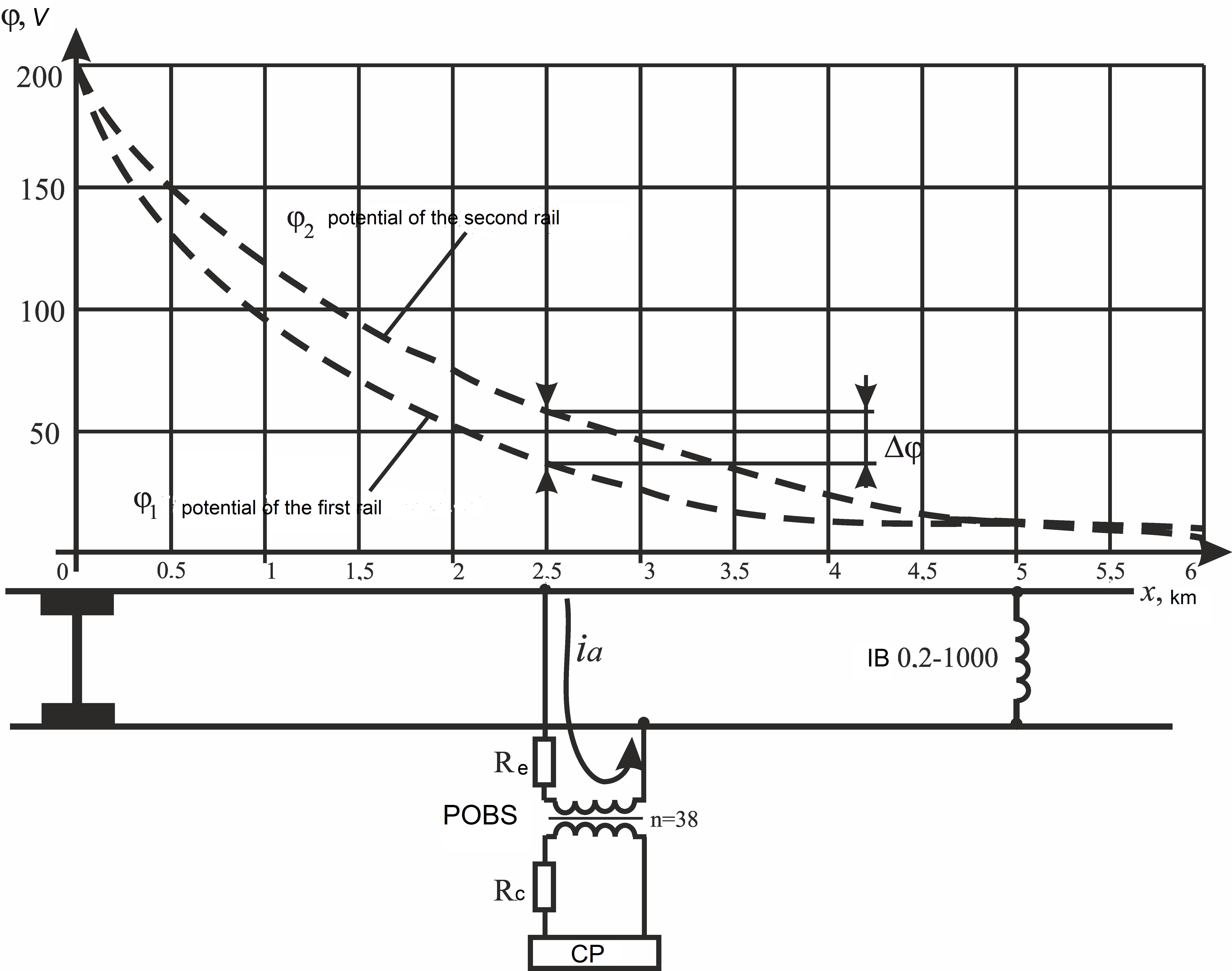
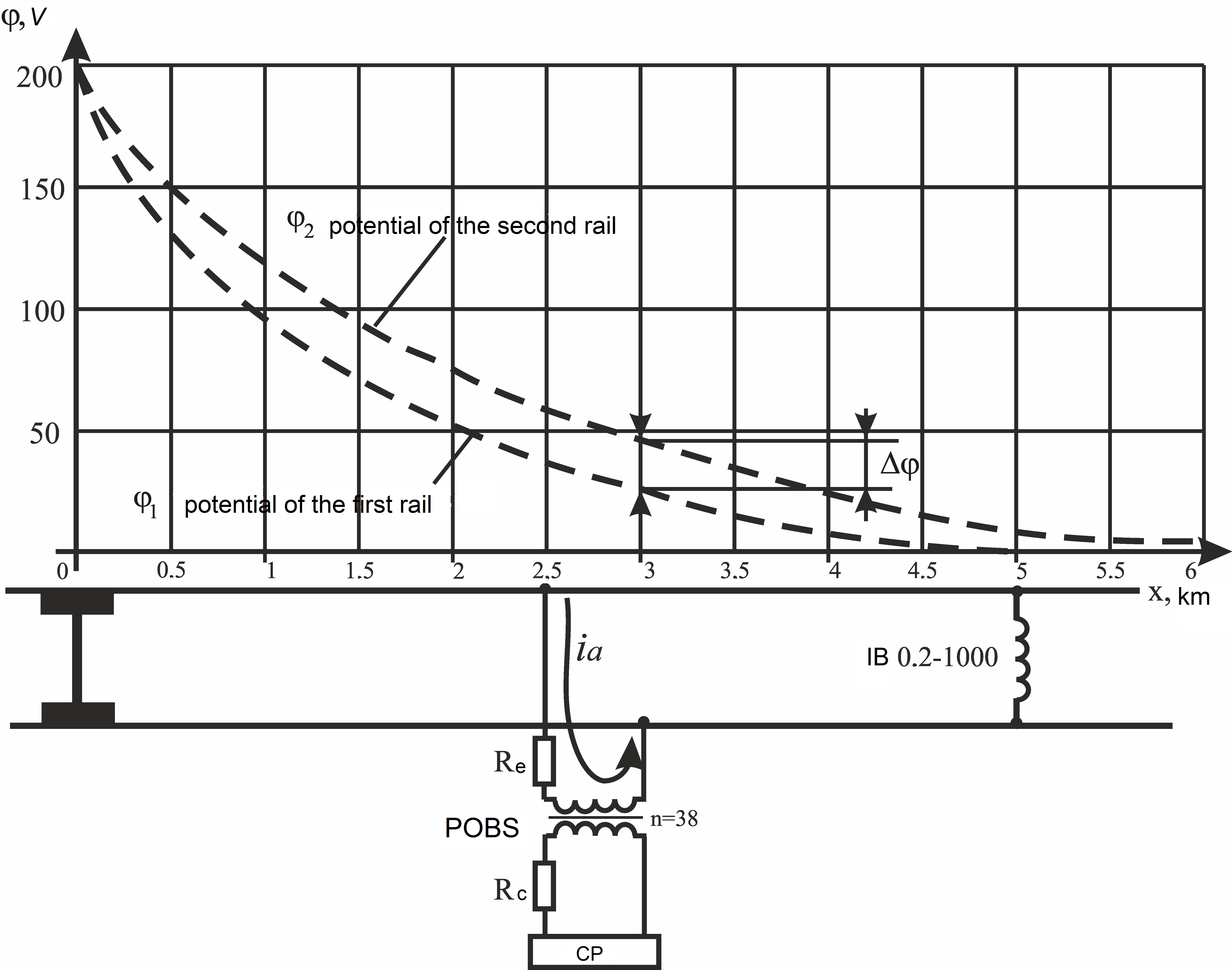
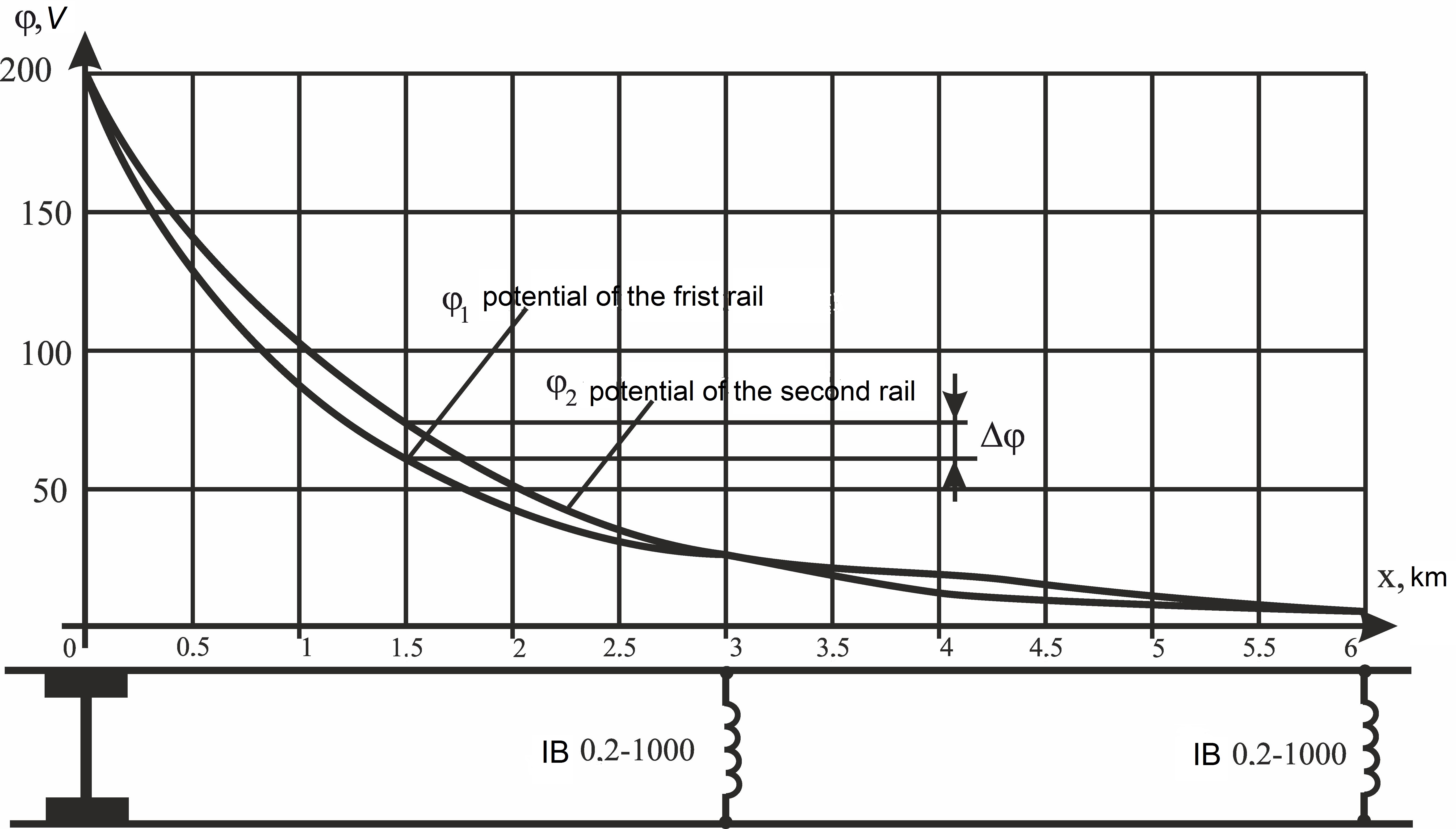
As can be
seen from the obtained dependencies (Fig. 2,
a, b),
the potential levels for each of the rails will be different. Their
difference will fall near the IBs, which align the potentials on the
rails. It should be noted that the potential difference ( )
in the middle of the section between the IB connection and the train
will be maximal [16].
)
in the middle of the section between the IB connection and the train
will be maximal [16].
а
b
c
d
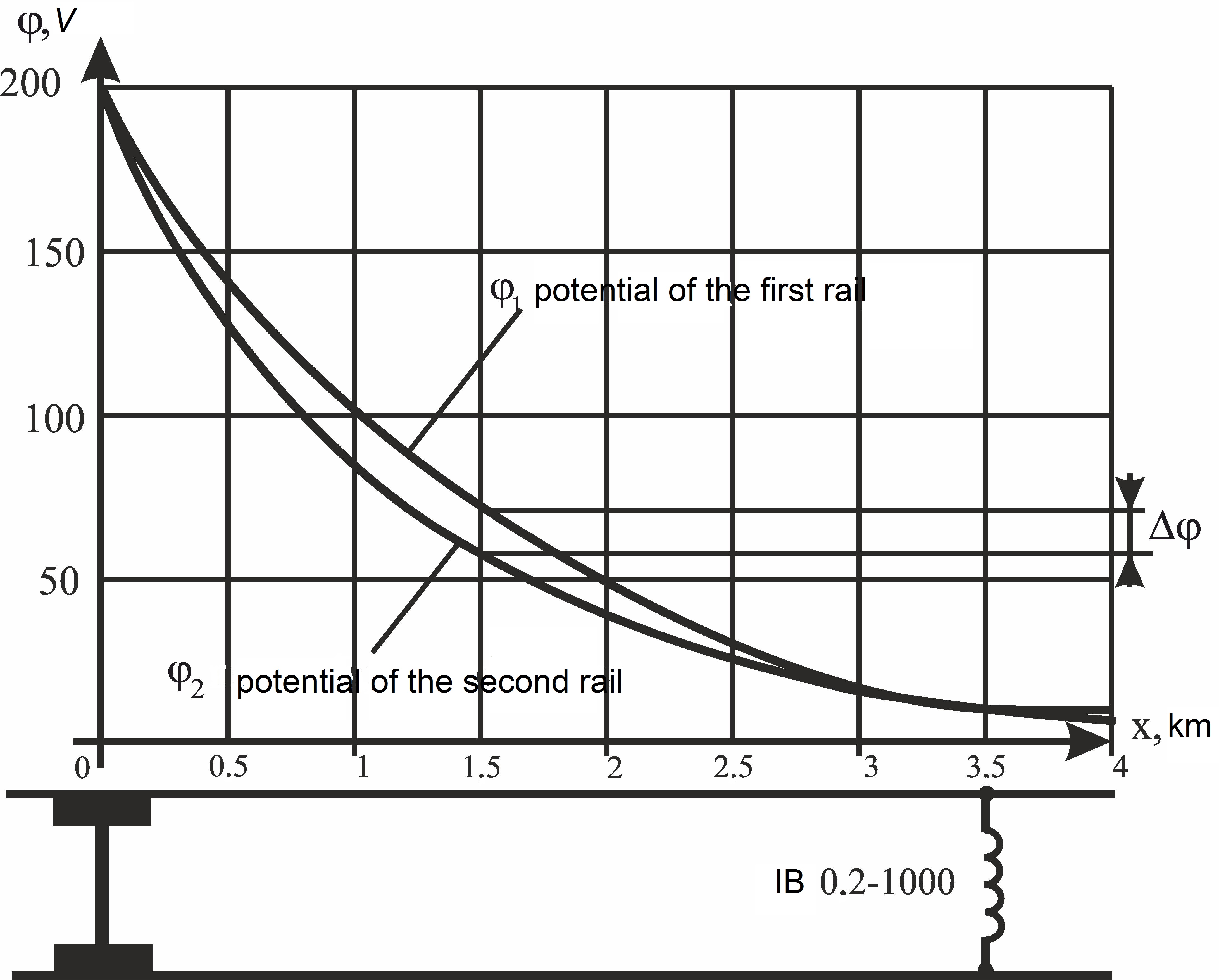
Fig.
2. Potentials railwise propagation with
IB:
а – installed every 5 km;
b – installed every 6 km;
c – installed every
3 km; d – installed every 3,5 km
For example,
in Figure 2, a,
which shows the potentials railwise propagation with IB installed
every 5 km
=
34 V. This indicator is quite high, since it will have a negative
impact on the operation of RC equipment. When installing IB every 6
km (Fig. 2, b)
will be 37 V.
In order to
reduce the potential difference, it was proposed to set equalizing
IB with a smaller interval. Figures 2, c,
d present
the curves of potentials railwise propagation when IB installed
every 3 km and 3.5 km, which show that at a distance of 1.5 km
will
be maximum and will equal 14 V. This indicator is completely
satisfactory for the operation of railway automation devices [17].
Figure 3
shows the dependence of the potential difference from the IB
installation interval. Curve 1 shows the change in the potential
difference with IB installed every 5 km, curve 2 – with IB
installed every 3 km. This graph confirms the expediency of the
proposed reduction in the IB installation interval, because the
maximum values
between the two curves vary significantly.
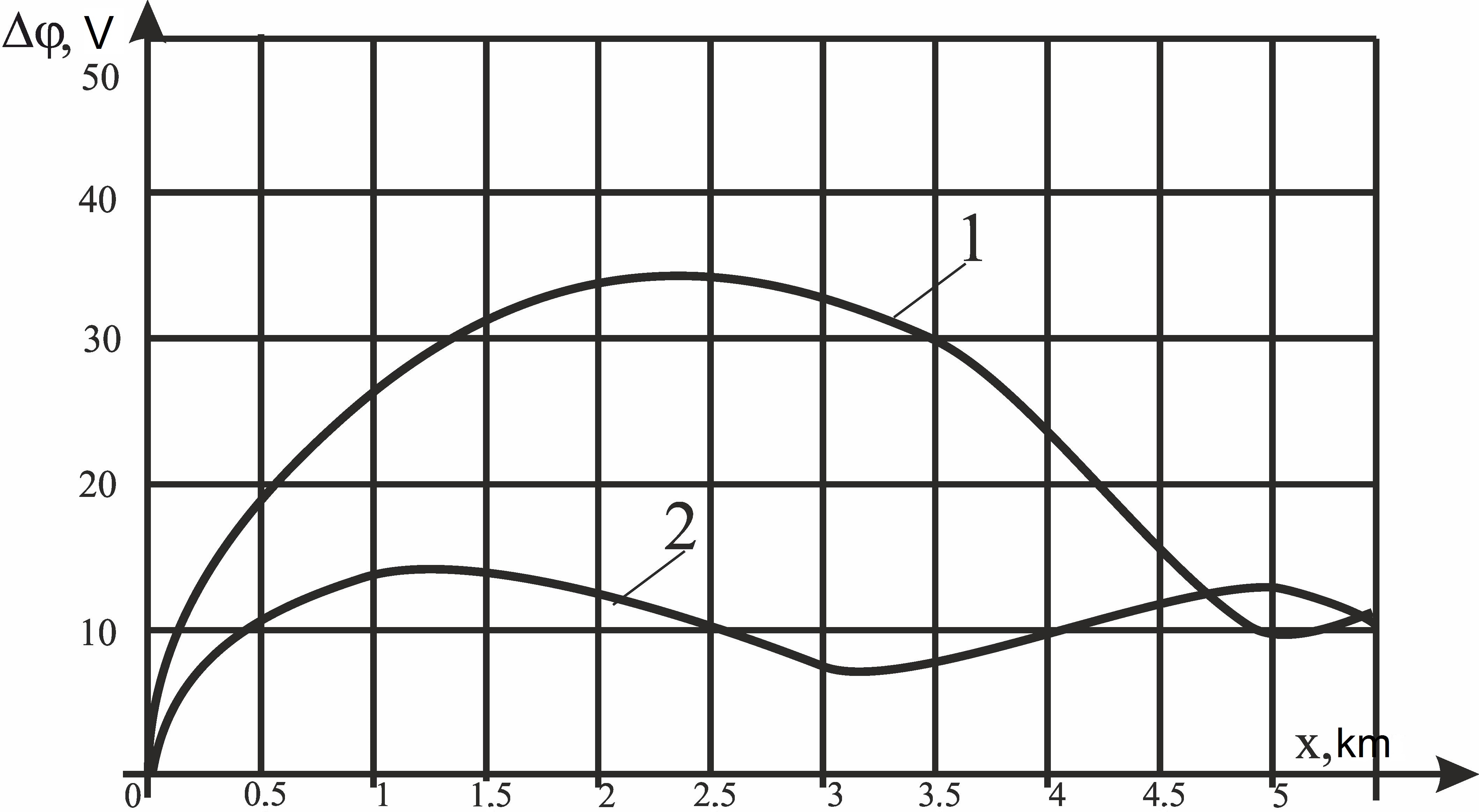
Fig.
3. Dependence of the potential difference
from the IB installation interval
Originality
and practical value
The proposed method for
calculating the propagation of potentials and currents in the rail
network of DC traction line is characterized by the representation
of the common ladder circuit of each rail as four-poles, taking into
account the grounding of the contact-line supports on the nearer
rail. It has allowed estimating the levels of asymmetry currents
that branch into the RC equipment. The obtained results can be used
in designing and re-equipping the running lines with new railway
automatics and supervisory systems (RAS), as well as for evaluating
the influence of high asymmetry currents on RAS systems operation.
Conclusions
The study of
impact of high levels of traction currents on the equipment of AB
systems was carried out. The method for calculating the propagation
of potentials and currents along the rails for the railway sections
with DC electric traction was improved. It consists in the study of
propagation of
 of each individual rail, which is
represented as HLC «rail-earth» and presented as a series of
T-shaped four-poles connected in cascade, taking into account the
grounding of the contact-line supports on the end rail.
of each individual rail, which is
represented as HLC «rail-earth» and presented as a series of
T-shaped four-poles connected in cascade, taking into account the
grounding of the contact-line supports on the end rail.
The proposed
method allowed carrying out the potentials railwise propagation
study with IB installed every 6 and 5 km (Fig. 2, a,
b). The
potential difference was too large for uninterrupted functioning of
RAS equipment. Therefore, it was proposed to shorten the IB
installation interval to 3 and 3.5 km [18]. As shown in the received
diagrams and in the resulting comparative graph in Figure 3,
the proposed solution is appropriate.
LIST OF REFERENCE LINKS
Аркатов,
В. С. Рельсовые цепи. Анализ работы и
техническое обслуживание / В. С. Аркатов,
Ю. А. Кравцов,
Б. М. Степенский. – Москва : Транспорт,
1990. – 295 с.
Атабеков,
Г. И. Теоретические основы электротехники
/ Г. И. Атабеков. – Москва : Энергия,
1978. – 591 с.
Гаврилюк,
В. И. Испытания новых типов подвижного
состава на электромагнитную совместимость
с устройствами сигнализации и связи
/ В. И. Гаврилюк, В. И. Щека, В. В. Мелешко
// Наука та прогрес транспорту. – 2015. –
№ 5 (59). – С. 7–15. doi:
10.15802/stp2015/55352.
Дыдышко,
П. И. Земляное полотно железнодорожного
пути : справочник / П. И. Дыдышко. –
Москва : Интекст, 2014. – 416 с.
Дьяконов,
В. П. Maple 10/11/12/13/14 в математических
расчетах / В. П. Дьяконов. – Москва : ДМК
Пресс,
2014.
–
800 с.
Каганов,
З. Г.
Электрические цепи с распределенными
параметрами и цепные схемы / З. Г.
Каганов. –
Москва : Энергоатомиздат, 1990. –
247 с.
Марквардт,
К. Г. Электроснабжение электрифицированных
железных дорог : учеб.
для вузов ж.-д. трансп. / К. Г. Марквардт.
– 4-е изд., перераб. и доп. – Москва :
Транспорт, 1982. – 528 с.
Разгонов,
А. П. Дослідження роботи рейкових кіл
та системи автоблокування на перевальних
ділянках з крутим профілем / А. П.
Разгонов, К. І. Ящук // Вісн. Дніпропетр.
нац. ун-ту залізн. трансп. ім.
акад. В. Лазаряна. – Дніпропетровськ,
2011. – Вип. 37. – С. 186–190.
Разгонов,
А. П. Оцінка впливу асиметрії тягового
струму на роботу перегінних рейкових
кіл / А. П. Разгонов,
К. І. Ящук // Безпека та електромагнітна
сумісність на залізн. трансп.
(S&EMC)
: тези VII
Міжнар. наук.-практ. конф. / Дніпропетр.
нац. ун-т залізн. трансп. ім. акад. В.
Лазаряна. – Дніпро, 2016. – С. 60.
Разгонов,
А. П. Профилактическое обслуживание
рельсовых цепей / А. П. Разгонов. –
Москва : Транспорт, 1980. – 324 с.
Щека,
В. І. Дослідження впливу зворотного
тягового струму на режими роботи
тональних рейкових кіл / В. І. Щека, І.
О. Романцев, К. І. Ящук // Вісн. Дніпропетр.
нац. ун-ту залізн. трансп. ім. акад. В.
Лазаряна. – Дніпропетровськ,
2012. – Вип. 42. – С. 24–28.
Щека,
В. І. Дослідження механізмів впливу
контактної мережі на рейкові кола / В.
І. Щека // Наука та прогрес транспорту.
– 2015. –
№ 3 (57). – С. 27–35.
doi: 10.15802/stp2015/46036.
Budnik,
K. Potential of the electric flow field produced in the earth by
stray currents from D.C. traction of complex geometry / K. Budnik,
W. Machczyński, J. Szymenderski //
Poznan
University of Technology Academic Journals. Electrical Engineering.
– 2016. – No. 85. – P. 29–40.
Gander,
W. Scientific Computing: An Introduction using Maple and MATLAB /
W. Gander, M. J. Gander, F. Kwok.
– Berlin : Springer-Verlag,
2014. – 905
p.
Lucca,
G. Estimating stray currents interference from DC traction lines on
buried pipelines by means a Monte Carlo algorithm / G. Lucca //
Electrical
Engineering.
– 2015. – Vol.
97. – Iss.
4.
– P. 277–286. doi:10.1007/s00202-015-0333-6.
Mariscotti,
A. Distribution
of the traction return current in AC and DC electric railway
systems / A. Mariscotti // IEEE Transactions on Power Delivery. –
2003. – Vol. 18. – Iss.
4. – P. 1422–1432.
doi:
10.1109/tpwrd.2003.817786.
Modelling
of earthing and return current systems of electric railways / A.
Zynovchenko, G. George, S. Körner, A. Stephan // Elektrische
Bahnen. – 2014. – No. Spec.
1.
– P.
132–136.
Verbert,
K. Fault diagnosis using spatial and temporal information with
application to railway track circuits / K. Verbert, B. De
Schutter,
R. Babuška // Engineering Applications of Artificial Intelligence.
– 2016. – Vol. 56.
– P. 200–211. doi:
10.1016/j.engappai.2016.08.016.
К. І. ЯЩУК1*
1*Каф.
«Автоматика, телемеханіка та зв’язок»,
Дніпропетровський національний
університет залізничного транспорту
імені академіка В. Лазаряна, вул.
Лазаряна, 2,
Дніпро, Україна, 49010, тел.
+38 (066) 647 54 89,
ел. пошта k.i.yaschuk@gmail.com,
ORCID 0000-0002-8606-5790
ДОСЛІДЖЕННЯ розповсюдження
потенціалів
уздовж рейок
Мета.
У науковій роботі передбачається
проведення дослідження розповсюдження
потенціалів та струмів уздовж рейок
із метою оцінки різниці потенціалів і
струму асиметрії у рейках, які можуть
здійснювати вплив на роботу систем
залізничної автоматики та телемеханіки.
Методика.
Для досягнення поставленої мети
застосовані методи аналізу та синтезу
електротехнічних розрахунків схем
рейкових кіл, математичного моделювання,
методи однорідних та неоднорідних
ланцюгових схем. Результати.
Проведені теоретичні дослідження
свідчать про те, що на гірських ділянках
залізниць з електричною тягою постійного
струму протікають струми дуже високих
рівнів, за яких навіть при номінальному
коефіцієнті асиметрії струм асиметрії
буде недопустимо великим. У результаті
переобладнання перегону системою
автоблокування з тональними рейковими
колами скоротилася кількість
дросель-трансформаторів, вирівнюючи
функції яких потребували подальшого
досконалого дослідження. Були отримані
епюри розповсюдження потенціалів
уздовж рейок при встановленні вирівнюючих
дросель-трансформаторів кожні 6 та 5
км. Отримані різниці потенціалів
виявилися зависокими для роботи систем
залізничної автоматики, тому було
проведено дослідження розповсюдження
потенціалів при інтервалі розташування
дросель-трансформаторів кожні 3 та 3,5
км, що значно покращило умови роботи
рейкових кіл. Наукова
новизна. Запропонований
метод розрахунку розповсюдження
потенціалів та струмів у рейковій
мережі перегону електричної тяги
постійного струму відрізняється
представленням загальної цепної схеми
кожної рейки у вигляді послідовно
з’єднаних в каскад Т-подібних
чотириполюсників із урахуванням
заземлення опор контактної мережі на
ближню рейку. Це дозволило оцінити
рівні струмів асиметрії, які відгалужуються
в апаратуру рейкових кіл та здійснюють
негативний вплив на їх роботу. Практична
значимість. Отримані
результати можуть використовуватися
при проектуванні та переобладнанні
перегонів новими системами залізничної
автоматики та телемеханіки, а також
для оцінки впливу високих струмів
асиметрії на роботу систем залізничної
автоматики.
Ключові
слова: тягові
струми; рейкові кола; дросель-трансформатор;
струм асиметрії; розповсюдження
потенціалів
Е. И. ящук1*
1*Каф.
«Автоматика, телемеханика и связь»,
Днепропетровский национальный
университет железнодорожного транспорта
имени академика В. Лазаряна,
ул. Лазаряна,
2, Днипро, Украина, 49010, тел. +38 (066) 647 54 89,
эл. почта k.i.yaschuk@gmail.com,
ORCID 0000-0002-8606-5790
ИССЛЕДОВАНИЕ РАСПРОСТРАНЕНИЯ
ПОТЕНЦИАЛОВ
ВДОЛЬ РЕЛЬСОВ
Цель.
В научной работе предполагается
проведение исследования распространения
потенциалов и токов вдоль рельсов с
целью оценки разности потенциалов и
тока асимметрии в рельсах, которые
могут оказывать влияние на работу
систем железнодорожной автоматики и
телемеханики. Методика.
Для достижения поставленной цели
применены методы анализа и синтеза
электротехнических расчетов схем
рельсовых цепей, математического
моделирования, методы однородных и
неоднородных цепных схем. Результаты.
Проведенные теоретические исследования
свидетельствуют о том, что на горных
участках железных дорог с электрической
тягой постоянного тока протекают токи
очень высоких уровней, при которых даже
при номинальном коэффициенте асимметрии
ток асимметрии будет недопустимо
большим. В результате переоборудования
перегона системой автоблокировки с
тональными рельсовыми цепями сократилось
количество дроссель-трансформаторов,
выравнивающие функции которых требовали
дальнейшего досконального исследования.
Были
получены эпюры распространения
потенциалов вдоль рельсов при установке
уравнивающих дроссель-трансформаторов
каждые 6 и 5 км. Полученные разности
потенциалов оказались слишком высокими
для работы систем железнодорожной
автоматики, поэтому было проведено
исследование распространения потенциалов
при интервале расположения
дроссель-трансформаторов каждые 3 и
3,5 км, что значительно улучшило условия
работы рельсовых цепей. Научная
новизна. Предложенный
метод расчета распространения потенциалов
и токов в рельсовой сети перегона
электрической тяги постоянного тока
отличается представлением общей цепной
схемы каждого рельса в виде последовательно
соединенных в каскад Т-образных
четырехполюсников с учетом заземления
опор контактной сети на ближний рельс.
Это позволило оценить уровни токов
асимметрии, которые ответвляются в
аппаратуру рельсовых цепей и оказывают
негативное влияние на их работу.
Практическая значимость.
Полученные результаты могут использоваться
при проектировании и переоборудовании
перегонов новыми системами железнодорожной
автоматики и телемеханики, а также для
оценки влияния высоких токов асимметрии
на работу систем железнодорожной
автоматики.
Ключевые слова: тяговые
токи; рельсовые цепи; дроссель-трансформатор;
ток асимметрии; распространение
потенциалов
REFEReNCES
Arkatov, V. S., Kravtsov, Y. A., &
Stepenskiy, B. M. (1990). Relsovyye
tsepi. Analiz raboty i tekhnicheskoye obsluzhivaniye.
Moscow: Transport.
Atabekov,
G. I. (1978). Teoreticheskiye osnovy
elektrotekhniki. Moscow: Energiya.
Havrilyuk,
V. I., Shcheka, V. I., & Meleshko, V. V. (2015). Testing new
types of rolling stock for electromagnetic compatibility with
signaling and communication devices. Science and
Transport Progress, 5 (59),
7-15. doi:10.15802/stp2015/55352
Dydyshko,
P. I. (2014). Zemlyanoye polotno
zheleznodorozhnogo puti [Manual].
Moscow: Intekst.
Dyakonov,
V. P. (2014). Maple 10/11/12/13/14 v
matematicheskikh raschetakh. Moscow:
DMK Press.
Kaganov,
Z. G. (1990). Elektricheskiye tsepi s
raspredelennymi parametrami i tsepnyye skhemy.
Moscow: Energoatomizdat.
Markvardt,
K. G. (1982). Elektrosnabzheniye
elektrifitsirovannykh zheleznykh dorog
[Guide]. Moscow: Transport.
Razgonov,
A. P., & Yaschuk, K. I. (2011). Analysis of track circuits work
and automatic signaling on pass section with steep gradient.
Bulletin of Dnipropetrovsk National University of Railway
Transport, 37, 186-190.
Razgonov,
A. P., & Yaschuk, K. I. (2016). Otsinka vplyvu asymetrii
tiahovoho strumu na robotu perehinnykh reikovykh kil. Proceedings
of the VII International Scientific and Practical Conference
«Safety and Electromagnetic Compatibility on Railway Transport«
(S&EMC), Rozluch, February16-19,
2016. 60-61. Dnipro: Dnipropetrovsk National University of Railway
Transport named after Academician V. Lazaryan.
Razgonov,
A. P. (1980). Profilakticheskoye
obsluzhivaniye relsovykh tsepey.
Moscow: Transport.
Sсheka,
V. I., Romancev, I. O., & Jasсhuk,
E. I. (2012). The investigation of reverse traction current
influence on tone track circuit modes. Bulletin of
Dnipropetrovsk National University of Railway Transport, 42,
24-28.
Shcheka,
V. I. (2015). Impact mechanisms research in the contact network on
rail track circuits. Science and Transport Progress,
3 (57), 27-35. doi:10.15802/stp2015/46036
Budnik,
K., Machczyński, W., & Szymenderski, J. (2016). Potential of
the electric flow field produced in the earth by stray currents
from D.C. traction of complex geometry. Poznan University
of Technology Academic Journals Electrical Engineering, 85,
29-40.
Gander,
W., Gander, M. J., & Kwok, F. (2014). Scientific
Computing: An Introduction using Maple and MATLAB.
Berlin: Springer-Verlag.
Lucca,
G. (2015). Estimating stray currents interference from DC traction
lines on buried pipelines by means a Monte Carlo algorithm.
Electrical Engineering, 97 (4), 277-286.
doi:10.1007/s00202-015-0333-6
Mariscotti,
A. (2003). Distribution of the traction return current in AC and DC
electric railway systems. IEEE Transactions on Power
Delivery, 18 (4),
1422-1432. doi:10.1109/tpwrd.2003.817786
Zynovchenko,
A., George, G., Körner, S., & Stephan, A. (2014). Modelling of
earthing and return current systems of electric railways.
Elektrische Bahnen, Special 1, 132-136.
Verbert,
K., De Schutter, B., & Babuška, R. (2016). Fault diagnosis
using spatial and temporal information with application to railway
track circuits. Engineering Applications of Artificial
Intelligence, 56,
200-211. doi:10.1016/j.engappai.2016.08.016
Prof.
A. P. Razghonov,
D. Sc. (Tech.), (Ukraine); Prof.
O. I. Stasiuk, D. Sc. (Tech.), (Ukraine)
recommended this article to be published
Received:
April 22, 2017
Accessed:
July 20, 2017
doi 10.15802/stp2017/109519 ©
K. I. Yashchuk, 2017