ISSN
2307–3489 (Print), ІSSN
2307–6666
(Online)
Наука та прогрес
транспорту. Вісник Дніпропетровського
національного університету залізничного
транспорту, 2017, № 3 (69)
ТРАНСПОРТЕ
БУДіВНицтво
ТРАНСПОРТНЕ
БУДІВНИЦТВО
UDC
[624.21.095:624.072.14]:625.1
S. V. KLUCHNIK1*
1*Industrial
Research Laboratory of Artificial
Structures, Dnipropetrovsk
National University
of Railway
Transport named after Academician V.
Lazaryan, Lazaryan St., 2,
Dnipro,
Ukraine, 49010, tel. +38 (050) 667
40 49, e-mail
ssser05@ukr.net,
ORCID
0000-0001-7771-8377
STRESS-STRAIN STATE OF BEAM STAGED
CONNECTION POINT
OF THE RAILWAY
BRIDGE TRACK-WAY
Purpose. The staged connections of the beams of
railway bridge track-way have the simplest design, but some design
flaws result in numerous defects. The purpose of the given work is to
research the actual stress-train state of the point of connection of
the stringers with the floor beams on condition of their staged
interposition. It is also necessary to determine possible effect of
coupled work of deck beam grid and booms on their stress-strain
state. Methodology. To reach the purpose of the study the
testing of the existing bridge was conducted. To measure strains
(stresses) in the span elements we used the strain gages glued to
flange angles of stringers and floor beams and to fillets of lower
flange angles of stringers in the points of their support on floor
beams. To measure deflections of the truss, stringers and floor beams
from static loads we used Aistov’s and Maksimov’s deflectometers,
that were installed on lower boom in the middle of span 0-1, as well
as on both stringers and floor beams in the middle of the span.
Deflectometers were fastened to the span and, by wire communication,
to the ground surface. Findings. Stress-strain state of
the point of connection of the stringers with the floor beams on
condition of their staged interposition was obtained and analyzed.
Analysis indicates that, apart from vertical bending of the stringers
and beams, there is a significant effect of horizontal bending of
floor beams and their torsion, that occur due to the coupled work of
track-way beams and top booms, both for P0 beam and for other beams.
Originality. Research of stress-strain state of metal
track-way staged beams while considering their coupled work with
bearing trusses. Practical value. While testing the span
under the train load, there are significant additional stresses from
horizontal bending of floor beams and their torsion in the floor beam
flanges. The appearance of these stresses is caused by inclusion of
stringers into coupled work with top booms. Appearing flaws in
stringers are caused by local stress concentration due to design
features of staged track way.
Keywords:
stringers; strain;
stress; floor
beams; metal
spans
Introduction
Deck spans allow to reduce the
consumption of metal, its width, and also the height of the supports
[1]. Since 1944 Proyektstalkonstruktsiya Design Institute proposed
new design projects of span structures with decks in the level of
the bottom and top booms. The deck spans have the truss spans of
44.0; 55.0 and 66.0 m and the main truss height of 8.5 m [7].
Distinctive features of PSK
deck spans are the reduction of the distance between the main
trusses to 4.0 m, the use of transverse cross-links of the main
trusses and the design change of the track-way beam grid, where
there is a staged connection of the track-way stringers and floor
beams [1]. The construction of stringer support on the floor beams
is shown in Fig. 1.
The staged
connections of the beams of railway bridge track-way have the
simplest design, but some design flaws result in numerous defects.
In the conditions of a staged connection of the track-way beams,
because of the large eccentricity between the axes of the stringers
and floor beams, the operation of the floor beams and the support
unit components is considerably complicated, and there occur local
overstress and cracks in the beam flange angles. Stitch rivets (or
bolts) joining the stringers to the floor beams also operate under
severe conditions.
Fig.
1. Construction
of beam grid
in PSK
deck
span structures
An
unfavorable
effect on
the metal
stress state
in the
places where
cracks appear
is caused
by the
beam
deformations,
that occur
when the
track-way
beams work
together with
the top
booms of
the main
trusses while
the entire
span is
loaded with
rolling stock.
Herewith the top booms are contracted, the
floor beams are bent in horizontal direction and are twisted, and at
the junction of the stringers and floor beams there occur an
additional angle of mutual rotation and deformation of the end
segments of the stringer flange angles, as well as deformation of
the top flange angles of the floor beams in the stringer-beam
intersections [7].
Unlike the one level track-way
beam connection, at the staged stringer-beam intersections the
fastening elements (rivets or bolts) and the beam flange angle seats
appeared not able to perceive the forces that arise from linear and
angular deformations of the beams.
Purpose
The problem that exists today
in the constructive solution of the staged connection of the track
way beams is in the need to improve the reliability of the
construction of the stringer-beam joint. To do this, it is necessary
to investigate the actual deformation-stressed state of the joint of
stringers with floor beams. This paper, in order to determine the
peculiarities of operation of the beam grid of the staged connection
point, presents the analysis of results of testing the real
structure. The purpose of the static tests was to measure the
stresses in stringers and floor beams of the track way and other
span elements under various test load settings. Particular attention
was paid to the stresses in the bottom flange angles of stringers
near their attachment to floor beams, since it is in these zones
that the main disorders are concentrated.
Methodology
The work was performed by the
Sectoral Scientific Research Laboratory (SSRL) of Artificial
Structures of the Dnepropetrovsk National University of Railway
Transport named after academician V. Lazaryan on the railway bridge
over the Mokraya Moskovka River on 186 km of the Krivoy
Rog-Volnovaha line.
The numbering of supports is
taken along the kilometers from Kryvyi Rih to Volnovakhi, starting
from No. 0. The bridge span structures are numbered in double Arabic
numerals in accordance with the numbers of the supports on which
they rest. The floor beams – along the kilometers, in accordance
with the name of the truss joints (P0-P8), and the stringers of span
structures – from left to right starting with one (B1 and B2).
To measure strains (stresses)
in the span elements we used the strain gages glued to flange angles
of stringers and floor beams and to fillets of lower flange angles
of stringers in the points of their support on floor beams.
To measure deflections of the
truss, stringers and floor beams from static loads we used Aistov’s
and Maksimov’s deflectometers, that were installed on lower boom
in the middle of span 0–1, as well as on both stringers and floor
beams in the middle of the span. Deflectometers were fastened to the
span and, by wire communication, to the ground surface.
Static tests
were carried out in «windows»
with a duration of 2 hours. Two shunting diesel locomotives ChME-3
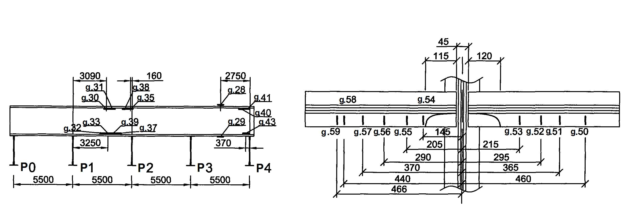
were used as a test load. Schemes of arrangement of strain gages
during the span structure static tests are shown in Fig. 2–4.
Findings
A
single-track
railway bridge
across the
Mokraya Moskovka
River on
186 km of
the Krivoy
Rog-Volnovakha
line is
located on
a straight
line in
plan and
site view. The
bridge clearance is spanned by two metal deck structures, with
design span of 44.0 m.
The railway bridge across the
Mokraya Moskovka River was built in 1903 according to one-span
scheme of 1×88 m, then subjected to disruption in 1920 and 1943. In
1948, the bridge was rebuilt according to the scheme of 2×44.0 m.
The total length of the bridge
is 107.96 m. According to the design, span structures are equal.
Span structures consist of two through riveted deck trusses, with a
triangular grid, as well as additional posts. The distance between
the trusses is 4.0 m, the truss height is 8.5 m. The trusses are
made according to the project of the Proyektstalkonstruktsiya for L7
load. The booms have H-shaped section. Longitudinal horizontal
connections between the trusses are located in the level of the top
and bottom booms, and the transverse connections in the even truss
points in the form of intersecting diagonals.
The track way consists of
staged-located I-section riveted stringers and floor beams.
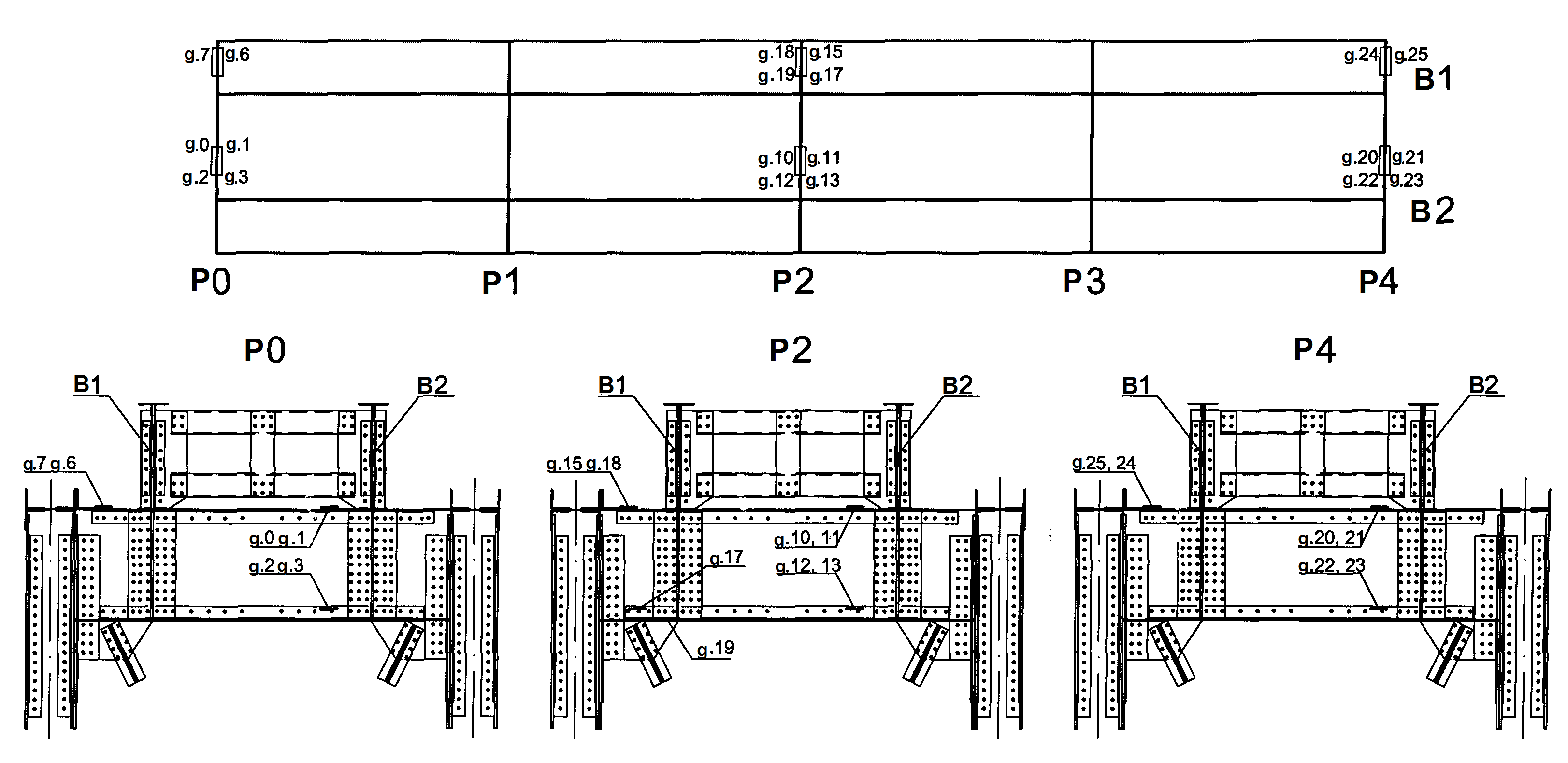
Fig.
2. Arrangement of
strain gages
during span
structure static
tests
a b
Fig.
3. Arrangement of strain gauges: on the stringer B1;
a
– on the left
stringer B 1
b
– on the left
stringer B1 in connection with P2
a b
Fig.
4 Arrangement of
strain gauges:
on the left
B1 and right
B2 stringers at
the point of
support
on
the floor beam
P4:
a
– left
stringer B1 in connection with P4
b
– right
stringer B2 in connection with P4
The stringer is fixed to the
floor beam with four bolts. The distance between the stringers is
2.0 m.
The bridge substructures are
double-track, massive. The buried abutments are built on a natural
foundation. The substructure underlying is granite, the intermediate
substructure is concrete, massive, built in 1948, the pole footing
is sunk shaft.
Prior to
testing, the bridge crossing was surveyed, which included full-scale
inspection of span structures, bridge substructures and supports,
survey of the river bed and approaches to the bridge, survey of the
state of the bridge and the track way on the bridge and approaches
[5, 8, 13].
The common defect of both span
structures is the corrosion of the horizontal sheets of the bottom
and top booms of the main trusses up to 1 mm, the paint peeling on
the main truss elements, the contamination of the horizontal
surfaces of the facings, the flanges with loose goods, and the
unsatisfactory drainage of moisture from the booms.
One of the most significant
detected defects is a disorder in the track way beam intersections.
Rivet ruptures, loose bolts,
development of cracks along the flange angles pad eyes of the
stringers at the points of their connection with the floor beams
have been registered in the survey since 1958. Some cracks were
drilled during the operation of the bridge, and later cuts were made
in the bottom flange angles of the stringers. However, the
development of cracks continues: along the left stringers at the
floor beam P3 on the span structure 0–1 and at the floor beams P1,
P3, P7 on the span structure 1–2 and along the right stringer at
the floor beam P5 on the span structure 0–1. The length of some
cracks after cutting the flange angle web reaches 128 mm. In the
bottom flange angles at the stringer-beam intersections P0 and P3,
the development of cracks continues and the length of the cracks
reaches 90 mm.
The loose bolts were found:
along the left stringers at the floor beams P1 – 4 pcs., P3 –
8 pcs., P6 – 6 pcs., P7 – 12 pcs. on the span structure 0–1
and at the floor beams P3 – 8 pcs., P7 – 6 pcs. on the span
1–2; and along the right stringers at the floor beams P5 – 4
pcs., P7 – 5 pcs. on the span of 0–1.
Gaps were found in
stringer-beam intersections: along the left stringers at the floor
beams P3 – 1.0 mm, P7 – 1.5 mm on the span structure 0–1
and at the floor beams P3 – 2.0 mm, P7 – 1 mm on the span 1-2;
and also, along the right stringers at the floor beams P5 – 1.0
mm, P7 – 1.0 mm on the span structure 0–1 and at the floor beam
P6 – 1.0 mm on the span structure 1–2.
Simultaneous presence of loose
bolts, cracks and looseness in beam support was found: along the
left stringers at the floor beams P3, P7 on the span structure 0–1
and at the floor beam P3 on the span structure 1–2; and along the
right stringer at the floor beam P5 on the span structure 0–1.
In addition, on the span 0–1
in the beam grid, the following defects were found:
1) wear of gaskets under angle
fishplates along the left stringers at the floor beams P1 – 1 mm,
P3 – 2 mm, P6 – 2 mm, P8 – 1 mm;
2) in the top flange angle of
the floor beam P2, there is a crack 85 mm long at the left stringer
intersection;
3) on the right stringer at the
junction of the floor beam P7 instead of 8 cut rivets there are
installed high-strength bolts;
4) curvature of the top flange
angles on the left stringer in panels 6–7 and 7–8 to 20 mm;
5) in the joints of the top
fishplates of the left stringers, in the panels 6–7 and 7–8 one
rivet is missing, the right stringers in the panel 6–7 2 rivets
are missing, in the panel 7–8 – one rivet.
On the span structure 1–2,
the wear of gaskets under angle fishplates along the left stringers
at the floor beams reaches: P2 – 1 mm, P3 – 1.5 mm, P5 – 2
mm, P7 and P8 – 1 mm.
In a number of places on the
span structure 0–1, on unchanged upper sway struts between the
stringers, there are local curvatures of the horizontal covers
resulting from the derailment of the rolling stock in 1985.
On the span 0–1 in the first
three panels, the longitudinal links between the main trusses have a
sagging of up to 30 mm and local curvatures, apparently resulted
from dropping downwards of the bridge deck debris in the course of
restoration work after the derailment in 1985.
Due to the presence of cracks
in the beam grid, there is a speed limit of up to 50 km/h on the
bridge.
Static
deflections were measured along the bottom flanges at the points L4
of both trusses. The highest deflection under the locomotive was 12
mm on both trusses. When converting to L7 load, the relative
deflection is 1/3000 lp,
which is below the limit value established by the norms.
When testing the track way
beams, their stress state was determined, taking into account the
joint work with the main trusses and the operation features of the
bottom flange angles of the stringers in the points of their
intersection with the floor beams. The loading patterns for the
tests are shown in Fig. 5.
For the end floor beam P0,
which is the most intensively involved in joint work with the truss
booms, an unfavorable test load setting became the loading according
to pattern 6.
In this case the greatest
stresses in the flange angles reached +49.5 (p. 2) MPa and –63.7
MPa (p. 1). The stress state of the floor beam P0 for various
loading patterns is given in Table 1.
Fig.
5. Test loading
patterns for span
0–1
Table 1
Stress
from the static load in the floor beam P0, MPa
|
No.
of scheme
|
Check
points
|
|
|
0
(in)
|
1
(in)
|
2
(out)
|
3
(out)
|
|
1
|
–20.2
|
–27.4
|
30.6
|
6.7
|
|
2
|
1.9
|
–21.2
|
23.1
|
–4.2
|
|
3
|
3.4
|
–47.1
|
42.0
|
–5.7
|
|
4
|
3.9
|
–41.5
|
36.8
|
–8.9
|
|
5
|
19.3
|
–40.1
|
31.6
|
–16.0
|
|
6
|
13.0
|
–63.7
|
49.5
|
–3.8
|
|
7
|
37.6
|
–32.5
|
17.4
|
–22.6
|
|
8
|
31.3
|
–22.6
|
12.5
|
–18.1
|
|
9
|
29.4
|
–18.9
|
10.7
|
–14.3
|
|
|
|
|
|
|
The analysis shows that in
addition to the vertical bending of the beam, there is a significant
influence of the horizontal bending and torsion of floor beams
arising from the joint work of the track way beams with the booms of
the main trusses, both at the P0 beam and at other beams.
The bearing test guidelines [3]
do not make it possible to determine the forces in the structural
elements of the track way beam joints, as they use the design
schemes in which the stringers are taken as simply supported, and
the floor beams – as working only in bending in the vertical plane
[6]. In fact, the stringers are continuous, and when subjected to a
temporary load, they tend to turn around the center of gravity. The
rotation of the support sections of the stringers corresponds to the
longitudinal displacements of their bottom surfaces and the same
horizontal displacement of the attached top surfaces of the floor
beams. Because of this, the floor beams work in horizontal bending
with torsion and at the same time prevent the turns of the support
sections of the stringers. The reason for this is the inclusion of
stringers in joint work with the truss booms [1].
When
the span
is loaded
with a
vertical load,
the compressed
truss booms
are shortened
in each
panel by
a value
of δ.
The presence of stringers, the length of
which remains practically unchanged under the load, prevents the
free movement of the floor beams, which are attached to the booms of
the main trusses. The difference of displacements Δδ of truss
booms and the track way stringers causes bending of the floor beams
in the horizontal plane.
The greatest
bending moments in the horizontal plane occur in the extreme floor
beams [1]. In the stringers the additional compressive forces
appear, and in the booms of the main trusses the compressive forces
are reduced. The bending of the stringers causes the torsion of the
floor beams, as well as the rotations of the attachment points and
the deformation of bends of the main truss booms in their plane.
Bending corresponds to shear forces, which decompose into
longitudinal forces leading to the displacement of the points of the
trusses.
When studying the stresses, the
special attention was paid to the determination of stresses in the
bottom flange angles of the stringers near their attachment to the
floor beams, since it is in these zones that the basic disorders
(cracks, looseness in support and attachment of beams) are
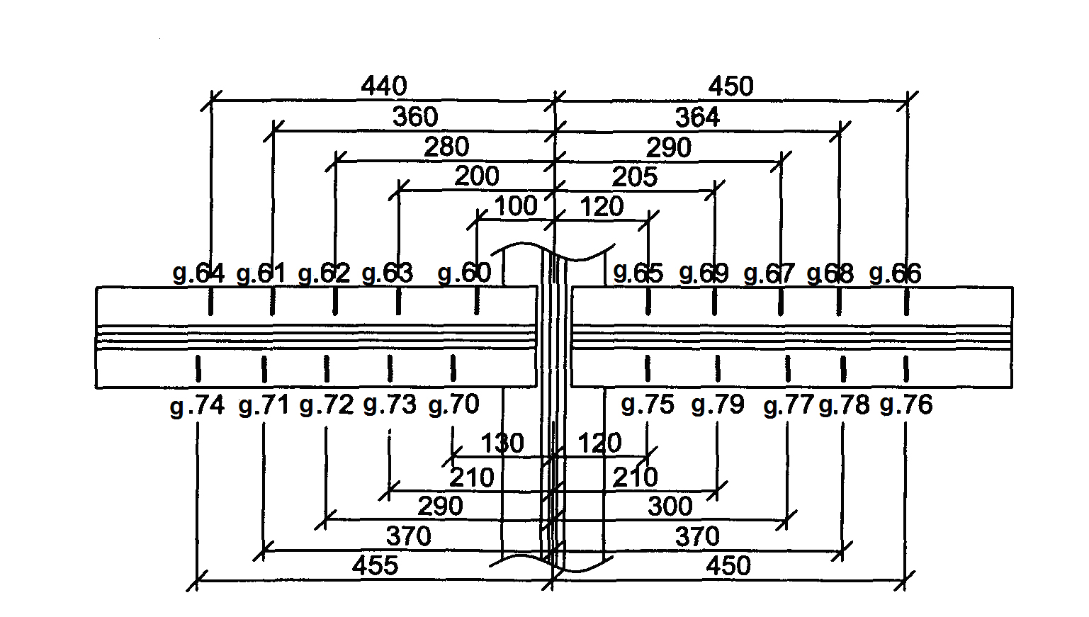
concentrated. For this purpose, the short base strain gauges were
pasted along the lower flange angles on the fillets of the stringers
B1 and B2 at their junction points to the floor beam P4.
Loading of the span structure
was carried out according to patterns 1–7 (Figure 5) with setting
of the first axis of the locomotive every 5.5 m.
The stressed state of the track
way beam elements of the staged connection is determined by the
lateral force and the bending moment acting in this zone. The moment
arises from the fact that the stringers are not continuous, and also
due to the features of the stringer-beam intersection operation
(presence of gaps in the support, fishplate wear, the leakage of the
stiffener edges, etc.). The maximum stresses in the stringer-beam
intersections occur when the span is loaded according to the pattern
9 and reach –136.4 MPa in p.60. For all loading patterns, the
highest experimental values of local stresses in the intersection of
stringers B1, B2 with floor beam P4 are given in Table 2.
Table 2
The
highest stresses in the intersections of stringers B1 and B2 with
floor beam P4 and stringer B1
(panel 1-2), MPa
|
Loading
patterns
|
B1
inner
|
B1
inner
|
B2
outer
|
B2
inner
|
B1
(panel
1-2)
|
|
|
σmax
|
σmin
|
σmax
|
σmin
|
σmax
|
σmin
|
σmax
|
σmin
|
top
|
bottom
|
|
1
|
–34.2
|
–2.5
|
–4.1
|
0
|
–5.3
|
0
|
9.2
|
2.9
|
–2.5
|
–8.9
|
|
2
|
40.0
|
2.5
|
–2.2
|
0
|
–4.3
|
–0.4
|
10.6
|
4.8
|
–16.8
|
10.4
|
|
3
|
38.4
|
0
|
4.1
|
0.4
|
–2.1
|
0
|
12.1
|
2.4
|
–29.1
|
4.9
|
|
4
|
–101.0
|
–0.8
|
–15.3
|
–0.4
|
–7.8
|
0
|
14.9
|
3.3
|
–23.7
|
12.8
|
|
5
|
–126.9
|
–19.2
|
–40.2
|
–0.4
|
–12.8
|
–1.4
|
17.3
|
1.4
|
–14.8
|
–4.4
|
|
6
|
–132.0
|
–18.3
|
–30.7
|
–5.4
|
–14.8
|
–2.5
|
–19.3
|
–0.9
|
–35.5
|
5.9
|
|
7
|
–133.0
|
–16.7
|
–31.2
|
–4.5
|
–13.1
|
–2.1
|
–19.8
|
–2.9
|
–28.1
|
19.7
|
|
8
|
–116.0
|
–19.5
|
–33.7
|
–7.6
|
–13.6
|
–0.5
|
26.5
|
7.4
|
–14.1
|
–8.6
|
|
9
|
–136.4
|
–6.1
|
–34.9
|
–5.2
|
14.4
|
0
|
27.8
|
5.9
|
–11.5
|
–11.8
|
Table
3
The
highest stresses in track way floor beams, MPa
|
Loading
pattern
|
Floor beams
|
|
|
P0
|
P2
|
P4
|
|
|
top
|
bottom
|
top
|
bottom
|
top
|
bottom
|
|
1
|
–27.4
|
(–6.1)
30.6
|
–8.5
|
10.8
|
–48.9
|
–4.9
|
|
2
|
–21.2
|
–4.2
|
–27.8
|
24.9
|
–42.0
|
–16
|
|
3
|
–47.1
|
–5.7
|
–54.2
|
47.6
|
–3.6
|
–17.5
|
|
4
|
–41.5
|
–8.9
|
–67.4
|
34.9
|
–9.8
|
–16.3
|
|
5
|
–40.1
|
–16.0
|
–78.7
|
33.9
|
–57.1
|
–2.5
|
|
6
|
–63.7
|
–3.8
|
–77.8
|
27.8
|
–38.8
|
–22.8
|
|
7
|
37.6
|
17.4
|
–71.7
|
23.6
|
35.1
|
2.0
|
|
8
|
31.3
|
12.5
|
–62.5
|
17.4
|
–32.7
|
3.1
|
|
9
|
29.4
|
10.7
|
–38.9
|
0.8
|
–66.0
|
–36.5
|
The stresses vary unevenly
along the angles. The greatest stresses occur, as a rule, at the
ends of the angles. In some cases, the maximum and local stresses in
the angles were at a distance of 80–100 mm from the angle
edges. In most cases, the change in stresses in the angles along
their length is characterized by a change in the stress sign.
In addition to measurements of
deformations (stresses) in the end floor beam P0, the stresses in
the left stringer B1 in the panel 1–2 and in the floor beams P2
and P4 were determined during the tests.
According to the measurement
results, in the stringer, in addition to stresses from the vertical
bending moment, there are stresses from the action of other factors
(horizontal bending, axial forces and torsion of the floor beam).
For the various loading
patterns, the highest stresses in the intersections of the stringers
B1 and B2 with the floor beam P4 and in the stringer B1 (panel 1–2)
are shown in Table 2. The highest stresses in the floor beams P0, P2
and P4 obtained during testing are given in Table 3.
Axial compressive stresses in
the stringers arise due to their joint work with the booms of the
main trusses. This causes a bending in the horizontal direction of
the floor beams. This is manifested the most for the floor beam P2
at its connection with the truss F1, and in the middle of the span
of this beam the effect of the horizontal bend is lower (see Table
3).
The maximum stresses from all
the loads are recorded in the floor beam P2 at its connection with
the truss F1 and amounted to -131.5 MPa at point 15 (pattern 9) and
+105.3 MPa at point 17 (pattern 9).
In the stringer B1, the maximum
stresses were recorded in the middle of panel 1-2 and amounted to
-35.5 MPa at point 30 (pattern 6) and +19.7 MPa at point 33 (pattern
7) (see Fig. 3 and Fig. 5).
Originality
and practical value
Vertical
deflections of the main trusses when the span structure was loaded
with a movable load (two sections of locomotive TEZ + 4-axle loaded
gondola cars) reached a value of 12.4 mm, 1/3500 lp.
While testing the span under the train load, there are significant
additional stresses from horizontal bending of floor beams and their
torsion in the floor beam flanges. The appearance of these stresses
is caused by inclusion of stringers into coupled work with top
booms.
Conclusions
Analysis of the experimental
data obtained during the testing of the track way beams allows
drawing the following conclusions.
The stressed state of the floor
beams P0, P2, P4 is determined mainly by vertical bending. Stresses
from horizontal bending and torsion appear from the joint work of
the track way beams with the booms of the main trusses.
The most significant stresses
are obtained from the horizontal bending in the floor beam P2 at the
point of its connection to the truss F1. The highest stress values
here are obtained in the angle of the top boom P2 at point 15 when
the span is loaded according to the pattern 9. In a greater degree
the horizontal bending of the floor beams affects the stress values
in the horizontal webs of the top flange angles with which the floor
beams are attached to the gusset plates of the upper longitudinal
ties between the main trusses. Here, the effect is that the span
structures installed on this bridge have very small distance from
the stringer axis to its connection to the truss.
A high level
of stresses in the top flanges of the floor beams explains the
appearance of a crack in the horizontal web of the top flange angle
in the section between the stringer and the truss [9,
11, 15].
The stress state in the middle
of the panel 1–2 of the stringer B1, where during the tests the
measurements were performed, is relatively low. Here the stress
values are no more than 30–40 MPa.
In those places where the
cracks have already appeared it was not possible to measure the
stresses. The measurements were taken mainly at the points of
support of the stringers on the floor beam P4, where cracks in the
bottom flange angles of the stringers were not observed during
inspection. In these places, a detailed study of the stress state
was carried out. The strain gauges were pasted at 32 points on
the fillets at the ends of the bottom flange angles on both sides of
each stringer every 80–100 mm.
Stresses in the angles proved
to be very high (up to 136.4 MPa). It should be noted that the
connection of stringers with a floor beam P4, obviously, is not the
most stressful point, because in this place, instead of the stringer
bottom angle fishplates there are extended gusset plates for break
connections. This is particularly significant as the design of the
span structures did not include the checks of the stresses in these
places. In other connections, where cracks are already observed in
the angles the stresses appeared to be even higher.
All this indicates that the
design of the intersection between the track way beams and the
staged arrangement of the stringers and floor beams applied on the
bridge is unsuccessful and requires an increase in the reliability
of the joint structures.
LIST
OF REFERENCE
LINKS
Бычковский,
Н. Н. Металлические мосты
/ Н. Н. Бычковский, А.
Ф. Данковцев ; Сарат. гос. техн. ун-т.
–Саратов, 2005.
– Ч. 1. –
364 с.
Гибаленко,
А. Н. Оценка живучести металлоконструкций
при моделировании факторов эксплуатации
/ А. Н. Гибаленко, Т. С. Трофимчук // Наука
та прогрес транспорту. –
2016. – № 2 (62).
– С. 119–128.
doi:
10.15802/stp2016/67327.
ГСТУ
32.6.03.111-2002. Експлуатація залізничних
мостів. Правила визначення
вантажопідйомності металевих прогонових
будов залізничних мостів. – Чинний
від 2001–12–05.
– Київ : М-во трансп.
України, 2003. – 382 с.
ДБН
В.1.2-15:2009. Споруди транспорту. Мости та
труби. Навантаження і впливи. – Чинний
від 2009–11–11. – Київ : Мінрегіонбуд
України, 2009. – 83 с.
ДБН
В.2.3-6:2009. Мости та труби. Обстеження і
випробування. – Чинний від 2009–11–11. –
Київ : М-во регіон. розвитку та буд-ва
України, 2009. – 43 с.
ДБН
В.2.3-14:2006. Споруди транспорту. Мости та
труби. Правила проектування. – Чинний
від
2007–02–01. – Київ : М-во буд-ва,
архітектури та житл.-комун. госп-ва,
2006. – 359 с.
Ефимов,
П. П. Проектирование
мостов / П. П.
Ефимов. –
Омск : Дантэя, 2006. – 111 с.
Інструкція
з визначення умов пропуску рухомого
складу по металевих та залізобетонних
залізничних мостах / Гол. упр. колійн.
госп-ва Укрзалізниці. – Київ : М-во
трансп. України, 2002. – 301 с.
Ключник,
С. В. Опыт эксплуатации этажной проезжей
части / С. В. Ключник, В.
В. Марочка // Проблемы и
перспективы развития железнодорожного
транспорта : тез.
докл. 72 Междунар.
науч.-практ.
конф. / Днепропетр. нац. ун-т
ж.-д. трансп. им. акад. В. Лазаряна. –
Днепропетровск, 2012. – С. 158.
Ключник,
С. В. Обзор варіантів підсилення
та ремонту балок проїзної частини
поверхового типу /
С. В.
Ключник, В. В. Марочка //
Мости та тунелі: теорія, дослідження,
практика. – 2014. – Вип.
5. –
С. 35–40.
Пат.
109806 Україна, МПК E
01 D 1/00, E
01 D 19/00, E
01 D 101/30.
Вузол спирання поздовжньої балки на
поперечну / Марочка Віталій Владиславович,
Ключник Сергій Владиславович ; заявник
та патентовласник Дніпропетр. нац.
ун-т залізн. трансп. ім. акад. В. Лазаряна.
– № u 2016
01940 ; заявл. 29.02.2016 ; опубл. 12.09.2016, Бюл. №
17.
Проблеми
ресурсу і безпеки експлуатації
конструкцій, споруд та машин [Electronic
resource]
: зб. наук. ст. / Ін-т електрозварювання
ім. Є. О. Патона НАН України. – Київ,
2015. – 816 с. – Available
at:
http://patonpublishinghouse.com/rus/compilations/resurs2015.
– Title
from the screen.
– Accessed
: 29.05.2017.
Шульман,
3. А. Испытания и мониторинг инженерных
сооружений / 3. А.
Шульман,
И.
3. Шульман.
– Днепропетровск,
ЛИРА,
2013. – 536
с.
Gibalenko,
A. N. Design requirements to structural steel durability based on
level of industrial facility corrosion hazard / A. N. Gibalenko, V.
Korolov, J. Filatov // Aktualnie problemy konstrukcji metalowych :
Abstr. II Polish-Ukrainian International Conference APMK (27.11–
28.11.2014) / University of Technology. – Gdansk, 2014. – Р.
98–102.
Ovchinnikov,
P. Sing
of finite
element
modeling for
determination
of buckling
possibility in
lengthwise
stiffeners of
orthotropic
plate for
bridge spans
under
operational
load / P.
Ovchinnikov, S.
Klyuchnik //
Мости та тунелі: теорія, дослідження,
практика. – 2012. – Вип. 5. – С. 130–135.
Rust,
I.
Sicherheit technischer Anlagen – Eine sozial wissenschaftliche
Analyse des Umgangs mit Risiken in Ingenieurpraxis und
Ingenieurwissenschaft
/ Ina Rust
; Kassel university.
– Kassel,
2004. –
394 p.
Weltschev,
M. Comparison of the operating life of tank containers, tank
vehicles and rail tank cars for the carriage of dangerous goods in
practice, analysis of causes of damage / М.
Weltschev, S. Schwarzer, F. Otremba // Chemical Engineering
Transactions. – 2013. – Vol. 31. – Р.
559–564. doi: 10.3303/CET1331094.
С. В. КЛЮЧНИК1
1ГНДЛ
штучних споруд, Дніпропетровський
національний університет
залізничного
транспорту імені академіка В. Лазаряна,
вул. Лазаряна, 2,
Дніпро, Україна, 49010,
тел. +38 (050) 667 40 49, ел. пошта
ssser05@ukr.net,
ORCID
0000-0001-7771-8377
ДЕФОРМАЦІЙНО-НАПРУЖЕНИЙ СТАН
ВУЗЛА ПОВЕРХОВОГО СПОЛУЧЕННЯ
БАЛОК
ПРОЇЗНОЇ ЧАСТИНИ
ЗАЛІЗНИЧНОГО МОСТА
Мета.
Поверхове сполучення балок проїзної
частини залізничних мостів найбільш
просте по конструкції, але внаслідок
конструктивних недоліків утворюються
численні дефекти. Метою даної роботи
є дослідження фактичного
деформаційно-напруженого стану вузла
сполучення поздовжніх балок із
поперечними при їх поверховому
розташуванні. Необхідно також визначити
можливий вплив спільної роботи поясів
ферм та балочної клітки мостового
полотна на їх деформаційно-напружений
стан. Методика.
Для досягнення поставленої мети
проведено випробування існуючого
моста. Для вимірювання деформацій
(напружень) в елементах прогонової
будови використовувалися тензорезистори,
наклеєні на поясних кутиках поперечних
і поздовжніх балок та на викружках
нижніх поясних кутиків поздовжніх
балок у місцях обпирання їх на поперечні
балки. Для вимірювання прогинів ферм,
поздовжніх та поперечної балок при
статичних випробуваннях використовувалися
прогиноміри Аїстова і Максимова, які
встановлювалися по нижніх поясах ферм
у середині прогону 0–1, а також на
обох поздовжніх та однією поперечною
балках із середини прольоту. Прогиноміри
кріпилися до прогінної будови та
з’єднувалися дротяними зв’язками з
поверхнею ґрунту. Результати.
Автором отримано і проаналізовано
деформаційно-напружений стан вузла
сполучення поздовжніх балок із
поперечними при їх поверховому
розташуванні. Аналіз показує, що крім
вертикального вигину балок має місце
значний вплив горизонтального вигину
поперечних балок та їх крутіння, що
виникають внаслідок спільної роботи
балок проїзної частини з верхніми
поясами головних ферм, як у балки П0,
так і в інших балок. Наукова
новизна. У роботі
проведено дослідження напружено-деформованого
стану металевих балок проїзної частини
поверхового розташування з урахуванням
спільної роботи балок із несучими
фермами. Практична
значимість. При
випробуванні прогонової будови поїзним
навантаженням у поясах поперечних
балок з’являються значні додаткові
напруги від горизонтального вигину
поперечних балок та їх крутіння. Поява
цих напружень пов’язана з включенням
поздовжніх балок у спільну роботу з
верхніми поясами ферм. Виникаючі дефекти
в поздовжніх балках пов’язані з
концентрацією місцевих напружень через
конструктивні особливості поверхової
проїзної частини.
Ключові слова: поздовжні
балки; деформація; напруження; поперечні
балки; металеві прогонові будови
С. В. КЛЮЧНИК1*
1*ОНИЛ
искусственных сооружений, Днепропетровский
национальный университет
железнодорожного
транспорта имени академика В. Лазаряна,
ул. Лазаряна, 2,
Днипро, Украина, 49010, тел.
+38 (050) 667 40
49,
ел. почта
ssser05@ukr.net,
ORCID 0000-0001-7771-8377
ДЕФОРМАЦИОННО-НАПРЯЖЕННОЕ
СОСТОЯНИЕ
УЗЛА ЭТАЖНОГО СОПРЯЖЕНИЯ
БАЛОК ПРОЕЗЖЕЙ
ЧАСТИ ЖЕЛЕЗНОДОРОЖНОГО
МОСТА
Цель.
Этажное сопряжение балок проезжей
части железнодорожных
мостов наиболее простое
по конструкции, но вследствие
конструктивных недостатков подвержено
многочисленным дефектам. Целью данной
работы является исследование фактического
деформационно-напряженного состояния
узла сопряжения продольных балок с
поперечными при их этажном расположении.
Необходимо также определить
возможное влияние совместной работы
поясов ферм и балочной клетки мостового
полотна на их деформационно-напряженное
состояние. Методика.
Для достижения
поставленной цели проведены испытания
существующего моста. Для измерения
деформаций (напряжений) в элементах
пролетного строения использовались
тензорезисторы, наклеенные на поясных
уголках поперечных и продольных балок
и на выкружках нижних поясных уголков
продольных балок в местах опирания их
на поперечные балки. Для измерения
прогибов ферм, продольных и поперечной
балок при статических испытаниях
использовались прогибомеры Аистова и
Максимова, которые устанавливались по
нижним поясам ферм в середине пролетного
строения 0–1, а также на обеих продольных
и одной поперечной балках в середине
пролета. Прогибомеры крепились к
пролетному строению и соединялись
проволочными связями с поверхностью
грунта. Результаты.
Автором получено и проанализировано
деформационно-напряженное состояние
узла сопряжения продольных балок с
поперечными при их этажном расположении.
Анализ показывает, что помимо вертикального
изгиба балок имеет место значительное
влияние горизонтального изгиба
поперечных балок и их кручения,
возникающие вследствие совместной
работы балок проезжей части с верхними
поясами главных ферм, как у балки П0,
так и у других балок. Научная
новизна.
В работе проведено исследование
напряженно-деформационного состояния
металлических балок проезжей части
этажного расположения с учетом совместной
работы балок с несущими фермами.
Практическая значимость.
При испытании пролетного строения
поездной нагрузкой в поясах поперечных
балок появляются значительные
дополнительные напряжения от
горизонтального изгиба поперечных
балок и их кручения. Появление этих
напряжений связано с включением
продольных балок в совместную
работу с верхними
поясами ферм. Возникающие дефекты в
продольных балках связаны с концентрацией
местных напряжений из-за конструктивных
особенностей этажной проезжей части.
Ключевые слова: продольные
балки; деформация; напряжения; поперечные
балки; металлические пролетные строения
REFERENCES
Bychkovskiy, N. N., &
Dankovtsev, A. F. (2005). Metallicheskiye
mosty. Saratov: Yuri Gagarin State
Technical University of Saratov.
Gibalenko,
O. M., & Trofymchuk, T. S. (2016). Metal
structures survivability assessment when simulating service
conditions. Science
and Transport Progress, 2(62),
119-128. doi:
10.15802/stp2016/67327
Ekspluatatsiia
zaliznychnykh mostiv. Pravyla vyznachennia vantazhopidiomnosti
metalevykh prohonovykh sporud zaliznychnykh mostiv, GSTU
32.6.03.111-2002 (2003).
Sporudy
transportu. Mosty ta truby. Navantazhennia i vplyvy, DBN
V.1.2-15:2009 (2009).
Sporudy
transportu. Mosty ta truby. Obstezhennia ta vyprobuvannia, DBN
V.2.3-6:2009 (2009).
Sporudy
transportu. Mosty ta truby. Pravyla proektuvannia, DBN
V.2.3-14:2006 (2006).
Yefimov,
P. P. (2006). Proektirovaniye mostov.
Omsk: Danteya.
Ukrzaliznytsia.
(2002). Instruktsiia z
vyznachennia umov propusku rukhomoho skladu po metalevykh ta
zalizobetonnykh zaliznychnykh mostakh. Kyiv: Ministry
of Infrastructure of Ukraine.
Kliuchnyk,
S. V., & Marochka, V. V. (2012). Opyt ekspluatatsii etazhnoy
proezzhey chasti. Proceedings of the 72
International Scientific & Practical Conference «Problems and
Prospects of Railway Transport Development«, April 19-20, 2012,
Dnipropetrovsk. 158.
Kliuchnyk,
S. V., & Marochka, V. V. (2014). Review of enhancement and
repair options for roadway
beams of two-level type.
Bridges and Tunnels: Theory, Research,
Practice, 5,
35-40.
Marochka,
V. V., & Kliuchnyk, S. V. (2016). UA
Patent No.109806. Ukrainian
Intellectual Property Institute (UKRPATENT).
Paton
Electric Welding Institute of the National Academy of Sciences of
Ukraine. (2015). Service life and
safety of structures, buildings and machinery.
Kyiv: Paton Publishing House. Retrieved
from
http://patonpublishinghouse.com/rus/compilations/resurs2015
Shulman,
Z. A., & Shulman, I. Z. (2013). Ispytaniya
i monitoring inzhenernykh sooruzheniy.
Dnipropetrovsk: LIRA.
Gibalenko,
A. N., Korolov, V., & Filatov, J. (2014). Design requirements
to structural steel durability based on level of industrial
facility corrosion hazard. Proceedings
of the II Polish-Ukrainian International Conference Aktualnie
problemy konstrukcji metalowych (APMK), November, 27-28, 2014,
Gdansk. Gdansk: University of
Technology.
Ovchinnikov,
P., & Kliuchnyk S. (2014). Using
of finite element modeling for determination of buckling
possibility in lengthwise stiffeners of orthotropic plate for
bridge spans under operational load. Bridges
and Tunnels: Theory, Research, Practice,
5,
130-135.
Rust,
I. (2004). Sicherheit technischer
Anlagen – Eine sozial wissenschaftliche Analyse des Umgangs mit
Risiken in Ingenieurpraxis und Ingenieur wissenschaft.
(Doctoral dissertation). Kassel University, Germany.
Weltschev,
M., Schwarzer, S., & Otremba, F. (2013). Comparison of the
operating life of tank containers, tank vehicles and rail tank cars
for the carriage of dangerous goods in practice, analysis of causes
of damage. Chemical Engineering
Transactions, 31,
559-564. doi:10.3303/CET1331094
Prof. V. D. Petrenko, D. Sc.
(Tech.), (Ukraine); Prof. V. Ye. Volkova, D. Sc. (Tech.), (Ukraine)
recommended this article to be
published
Received:
Feb. 10, 2017
Accessed: May 17, 2017